Cisco Routers

Cisco routers provide access to applications and services, and integrate technologies

IP Phone - Cisco

IP phone takes full advantage of converged voice and data networks, while retaining the convenience and user-friendliness you expect from a business phone...

WAN - Cisco Systems

Transform your WAN to deliver high-performance, highly secure, and reliable services to unite campus, data center, and branch networks.

EtherChannel - Cisco Systems

EtherChannel provides incremental trunk speeds between Fast Ethernet, Gigabit Ethernet, and 10 Gigabit Ethernet. EtherChannel combines multiple Fast ...

Looking Toward the Future - Cisco Systems

Looking Toward the Future by Vint Cerf. The Internet Corporation for Assigned Names and Numbers (ICANN) was formed 9 years ago....

Pages

Saturday, September 22, 2012

Network Diagram Templates

Here are a few simple tips to help you create quality, professional-looking network diagrams.

Use Multiple Pages
The number one mistake in many network diagrams is an attempt to convey too much information on one page. Visio allows use of multiple pages just like an Excel workbook with many worksheets, so consider using multiple drawing sheets for different purposes.

Make Use of Border Templates
A border template can make your life a little easier by providing a way to track changes to your diagrams. In your template include sections for author name, version number, date, page number, and any other fields that will be useful. Most of the fields can automatically update themselves - more information on that can be found on the Microsoft website here.

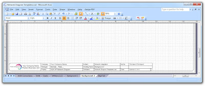
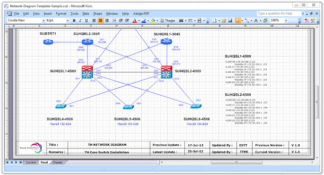
For example, if you want a background page that displays your company logo, or a title block that contains fields such as the creation date of a drawing, subject, Author, Drawing name, Filename, Manager, create these items and assign them to the foreground page. Let us see the example of what are on the visio after creating the Network Diagram Templates:
Network Diagram Templates Background 
Network Diagram Templates Background Network Diagram Templates BackgroundTemplates Background Insert Page
Diagram Templates Background

Friday, April 6, 2012

Cisco WLAN design

      With most WLAN designs, security is the first capability folks worry about. Fortunately, WLAN technology contains robust security features with viable authentication and encryption mechanisms. A security solution can be designed in a variety of ways, however. This tip provides some best practices for designing effective security architectures.


       We will cover specific design aspects of the Cisco WLAN solution utilizing controller-based architectures. These design best practices have been developed over the course of multiple design initiatives with the Cisco solution and primarily from lessons learned from deploying the Cisco solution. Most of the information is related to the Cisco solution, but some of the lessons learned and best practices relate to the process behind deploying the designs.

User considerations
       In most organizations, the user community dictates the security architecture. It is not a one-size-fits-all approach. The recommended approach is to identify the user communities that will utilize the WLAN system and design the security accordingly.

As a foundation, the following user communities are a good place to start:
  • Employees/visiting employees -- require access to corporate applications and need those applications to be secure
  • Contractors -- on site temporarily, but for an extended period of time; require access to some corporate applications (other than just Internet)
  • Guests -- need access to Internet only


Tuesday, April 3, 2012

Multi-Protocol Label Switching (MPLS)

   This article identifies Multi-Protocol Label Switching (MPLS) technology components, describes their functionality, and illustrates the value they provide in Service Provider environments.

       MPLS was initially targeted for Service Provider customers; however, Enterprises have begun to show interest in deploying this technology. This document can apply to large Enterprise customer whose networks resemble Service Provider networks in the following areas:
  • Size of the network
  • Offer "internal services" to different departments within the Enterprise
   MPLS compliments IP technology. It is designed to leverage the intelligence associated with IP Routing, and the Switching paradigm associated with Asynchronous Transfer Mode (ATM). MPLS consists of a Control Plane and a Forwarding Plane. The Control Plane builds what is called a "Forwarding Table," while the Forwarding Plane forwards packets to the appropriate interface (based on the Forwarding Table).
   The efficient design of MPLS uses Labels to encapsulate IP packets. A Forwarding Table lists Label Values, which are each associated with determining the outgoing interface for every network prefix. Cisco IOS Software supports two signaling mechanisms to distribute labels: Label Distribution Protocol (LDP) and Resource Reservation Protocol/Traffic Engineering (RSVP / TE).

MPLS comprises the following major components:
  1.  MPLS Virtual Private Networks (VPNs)—provides MPLS-enabled IP networks for Layer 3 and Layer 2 connectivity. Includes two major components:    1.  Layer 3 VPNs—based on Border Gateway Patrol    2.  Layer 2 VPNs—Any Transport over MPLS (AToM)
  2. MPLS Traffic Engineering (TE)— provides an increased utilization of network bandwidth inventory and for protection services
  3. MPLS Quality of Service (QoS)— buildings upon existing IP QoS mechanisms, and provides preferential treatment to certain types of traffic, based on a QoS attribute (i.e., MPLS EXP).
MPLS VPNs (Layer 3 VPNs)
   Layer 3 VPNs or BGP VPNs have been the most widely deployed MPLS technology. They use Virtual Routing instances to create a separate routing table for each subscriber, and use BGP to establish peering relations and signal the VPN-associated labels with each of the corresponding Provider Edge (PE) routers. This results in a highly scalable implementation, because core (P) routers have no information about the VPNs.

   BGP VPNs are useful when subscribers want Layer 3 connectivity, and would prefer to offload their routing overhead to a Service Provider. This ensures that a variety of Layer 2 interfaces can be used on either side of a VPN. For example, Site A can use an Ethernet interface, while Site B uses an ATM interface; however, Sites A and B are part of a single VPN.

It is relatively simple to implement multiple topologies with router filtering, including a Hub & Spoke or Full Mesh:
  • Hub and Spoke—central site is configured to "learn" all the routes from the remote sites, while the remote sites are restricted to "learn" routes only from the central site.
  • Full Mesh topologies would result in all the sites having the ability to "learn" or import routes from every other site.
    Layer 3 VPNs have been deployed in networks that have as many as—seven hundred PE routers. Service Providers are currently providing up to five hundred VPNs, with each VPN containing as many as one thousand sites. A wide variety of routing protocols are available deploy on the subscriber access link (i.e. CE to PE link). These include Static Routes, BGP, RIP and Open Shortest Path First (OSPF). Most VPNs have been deployed with Static Routes, followed by BGP Routing.

   Layer 3 VPNs offer advanced capabilities, including Inter-AS and Carrier Supporting Carrier (CSC). These provide hierarchical VPNs, allowing a Service Provider to provide connectivity across multiple administrative networks. Currently, initial deployments of such functionality are becoming more widespread.
Download MPLS FLASH PRESENTATION here Full Mesh, Point to Point

Sunday, April 1, 2012

Cisco Catalyst 6500 Series Supervisor Engine 720

The Cisco® Catalyst® 6500 Series Supervisor Engine 720 is a family of Supervisor Engine(s) designed to deliver scalable performance and rich set of IP features in hardware. Its hardware-based feature set enables applications such as traditional IP forwarding, Layer 2 and Layer 3 Multiprotocol Label Switching (MPLS) VPNs, Ethernet over MPLS (EoMPLS) with quality of service (QoS) and security features. The Supervisor engine 720 integrates a high-performance 720 Gbps crossbar switch fabric with a forwarding engine in a single module, delivering 40 Gbps of switching capacity per slot (enabling 4-port 10GE and 48-port 10/100/1000 density line cards). With hardware-enabled forwarding for IPv4, IPv6 and MPLS, the system performance is capable of 400 Mpps for IPv4, 200 Mpps for IPv6 traffic, with features and 1024 VRFs each populated with up to 700 routes/VRF for MPLS


NIC Teaming and Cisco Switch Config

Server Configuration
       Server Access port configuration 
Server access ports typically fall into three categories:
  1. Normal servers which require simple gigabit connectivity with fail on fault cards (what HP calls Network Fault Tolerance – NFT)
  2. High bandwidth servers which require two gigabit throughput using aggregation
  3. VMWare servers which require special configuration 
Some initial thoughts
       Nowadays auto-negotiation of speed and duplex works well with server gigabit interfaces so do not try and set the speed or duplex manually. One reason is auto-negotiation enables the cable-tester built into some gigabit Ethernet modules to function.
For example:
switch#test cable-diagnostics tdr interface gi1/2/1
TDR test started on interface Gi1/2/1
A TDR test can take a few seconds to run on an interface
Use 'show cable-diagnostics tdr' to read the TDR results.
switch#show cable-diagnostics tdr interface gi1/2/1
TDR test last run on: August 06 13:58:00
Interface Speed     Pair Cable length Distance to fault   Channel Pair status
             --------- ----- ---- ------------------- ------------------- ------- ------------
Gi1/2/1   1000  1-2  0    +/- 6  m       N/A                Pair B  Terminated 
                       3-6  0    +/- 6  m       N/A                 Pair A  Terminated 
                       4-5  0    +/- 6  m       N/A                 Pair D  Terminated 
                       7-8  0    +/- 6  m       N/A                 Pair C  Terminated 


       If a server comes in at 100 Mbps and the server is also set to auto/auto, it is likely that there is a cable fault (gigabit requires all pairs to be terminated where 100 Base-T does not).
       Access ports should also be set to spanning-tree portfast as per established practice.
       Port-security is also worth mentioning as it is NOT compatible with dual-homed servers using HP’s network teaming software. Any cable fault on NIC 1 results in the MAC address shifting over to NIC 2’s port and the switch sees this as a security violation, blocks traffic and generates this syslog message.

Normal ServersSwitch Configuration

interface <interface name>
 switchport
 !Set an access VLAN
 switchport access vlan <###>
 !Force access mode
 switchport mode access
 !Set an acceptable broadcast storm level
 storm-control broadcast level 0.10
 !Port-security is not compatible with dual-homed servers
 no switchport port-security
 no switchport port-security maximum
 no switchport port-security violation restrict
 spanning-tree portfast
end

Server configuration
       The default configuration on HP servers for a teaming interface is Type: Automatic and Transmit: Automatic. This configuration will, on non-etherchannel switch ports, default to Transmit Load Balancing with Fault Tolerance (TLB). One NIC will transmit and receive traffic whilst the other will only transmit.
       From a network point of view this makes troubleshooting difficult, as transmit traffic is spread over two NICs with two MAC addresses and receive traffic is directed to just one NIC depending on what NIC responds to ARP requests. 
Our PREFERRED configuration is to use either: 
NFT Teaming Configuration
NFT Teaming with preference configuration
       Two servers that are known to exchange a lot of traffic with each other but do not use Etherchannel should use NFT with preference and ensure that the active NICs on both servers go to the same switch.

High Bandwidth Servers

Switch Configuration

Note: most settings MUST match between all ports in the same Etherchannel group (e.g. storm-control; access mode; and vlan).
interface <interface name> switchport
 !Set an access VLAN switchport access vlan <###>
 !Force access mode switchport mode access
 !Set an acceptable broadcast storm level storm-control broadcast level 0.10
 !port-security is not compatible with channelling  no switchport port-security
 no switchport port-security maximum
 no switchport port-security violation restrict
 !Force LACP & enable as passive mode channel-protocol lacp
 channel-group <#> mode passive
 spanning-tree portfast
 !Force flowcontrol off to stop any channelling issues
 !Intel cards default to no flow control; HP on-board default to on

 flowcontrol receive off
 flowcontrol send off
end


Sample output showing two links being aggregated:
switch#show int po100 etherchannel
Port-channel100   (Primary aggregator)

Age of the Port-channel   = 1d:01h:38m:34s
Logical slot/port   = 14/4          Number of ports = 2
HotStandBy port = null
Port state          = Port-channel Ag-Inuse
Protocol            =   LACP
Fast-switchover     = disabled

Ports in the Port-channel:

Index Load Port    EC state    No of bits
------+------+------+------------------+-----------
  1     FF   Gi1/2/1  Passive    8
  0     FF   Gi2/2/1  Passive    8

Time since last port bundled:    0d:00h:00m:05s    Gi1/2/1
Time since last port Un-bundled: 0d:00h:00m:33s    Gi1/2/1
Server configuration
       The default configuration on HP servers for a teaming interface is Type: Automatic and Transmit: Automatic. This configuration will attempt to negotiate an etherchannel using LACP and if this fails to use Transmit Load Balancing (TLB). As long as the port-channel and its corresponding physical interfaces are configured correctly the default configuration seems to work well. Although TLB is not our preferred failback connection type, there does not appear to be a way to enable channelling with NFT fallback.

Default Teaming Configuration
Successful LACP negotiation
Unsuccessful LACP negotiation
Other features such as duplex/speed and flowcontrol are best left at defaults.

Jumbo Frames
       Jumbo frames may improve performance of some applications, but no testing has been done at the time of writing to verify whether they introduce problems either locally or to remote users on a 1500 byte MTU WAN connection or whether they do indeed improve performance as much as some would believe. http://www.nanog.org/mtg-0802/scholl.html may be useful reading.
       Jumbo frames are also incompatible with HP’s TCP Offload Engine (TOE) NICs so jumbo frames may suffer from reduced throughput. More testing and investigation will be required before coming to any firm conclusions or recommendations. Therefore at the current time, our recommendation for host access ports is to use a standard 1500 byte MTU / 1518 byte frame size.
       However, since every trunk link on a LAN has to support the highest MTU, it is worth building the LAN’s trunk links to support a high MTU even if the access ports still run at 1514 bytes. This leaves the option open for later adoption at the host layer and allows easy adoption of some devices that require a high MTU such as Fibrechannel over IP. 
Saturday, March 17, 2012

Hot Standby Router Protocol (HSRP)

Hot Standby Routing Protocol or HSRP, is a Cisco proprietary protocol that allows two or more routers to work together to represent a single IP address for a particular network. HSRP, as well as Virtual Route Redundancy Protocol (VRRP) are considered high-availability network services that allow for almost immediate fail over to a secondary interface when the primary interface becomes unavailable.

HSRP is a fairly simple concept that works by having one router within an HSRP group be selected as the primary, or active router.
That primary will handle all routing requests while the other routers within the HSRP group simply wait in a standby state. These standby routers remain ready to take on all of the traffic load if the primary router becomes unavailable. In this scenario, HSRP provides high network availability since it routes IP traffic without depending on a single router.

The hosts that use the HSRP address as a gateway never know the actual physical IP or MAC address of the routers in the group. Only the virtual IP address that was created within the HSRP configuration along with a virtual MAC address is known to other hosts on the network.
Hot Standby Router Protocol

Basic HSRP Configuration
       Before we discuss more advanced HSRP concepts, lets create a basic HSRP configuration to get an idea of how this all works. For this scenario we will use a topology consisting of just two core switches. Keep in mind that one or both of these routers. But for this discussion let’s just refer them as core switches.

       CORESW1-6509 and CORESW2-6509 will both be configured to be in standby group 1. The HSRP address will be given an IP address of 156.50.196.1/24. All hosts on the segment and in the VLAN will use this address as their default gateway.

CORESW1-6509(config)#interface VLAN 100
CORESW1-6509(config-if)#ip address 156.50.196.2
CORESW1-6509(config-if)#standby 1 ip 156.50.196.1
CORESW2-6509(config)#interface VLAN 100
CORESW2-6509(config-if)#ip address 156.50.196.3
CORESW2-6509(config-if)#standby 1 ip 156.50.196.1

       To see the status of HSRP use the command show standby. This is the first command you should run to ensure that HSRP is running and configured properly.

CORESW1-6509#show standby
VLAN 100 - Group 1
Local state is Standby, priority 100
Hellotime 3 sec, holdtime 10 sec
Next hello sent in 0.776
Virtual IP address is 156.50.196.1 configured
Active router is 156.50.196.3, priority 100 expires in 9.568
Standby router is local
1 state changes, last state change 00:00:22

CORESW2-6509#show standby
VLAN 100 - Group 1
Local state is Active, priority 100
Hellotime 3 sec, holdtime 10 sec
Next hello sent in 2.592
Virtual IP address is 156.50.196.1 configured
Active router is local
Standby router is 156.50.196.2 expires in 8.020
Virtual mac address is 0000.0c07.ac05
2 state changes, last state change 00:02:08

       We can see that CORESW2-6509 has been selected as the Active core switch ("Local state is Active"), the virtual core switch's IP is 156.50.196.1, and CORESW1-6509 is the standby core switch.

Controlling the Active HSRP Router
       There are more HSRP values that you'll need to change from time to time to ensure complete control over your network traffic. For example, what if we wanted CORESW1-6509 to be the Active core switch instead of CORESW2-6509? To force a particular core switch to be the active core switch in an HSRP group you will need to use the priority command.
       The default
priority is 100. The higher priority will determine which core switch is active. If both core switchs are set to the same priority, the first core switch to come up will be the active core switch.

Using our example above, this is how the commands would look.

CORESW1-6509(config)#interface VLAN 100
CORESW1-6509(config-if)#ip address 156.50.196.2
CORESW1-6509(config-if)#standby 1 ip 156.50.196.1
CORESW1-6509(config-if)#standby 1 priority 200 <-- Add this to force CORESW1-6509 to be active 

CORESW2-6509(config)#interface VLAN 100 
CORESW2-6509(config-if)#ip address 156.50.196.3 
CORESW2-6509(config-if)#standby 1 ip 156.50.196.1 


Keeping the Active Core switch Active 
      In our scenario above, if CORESW1-6509 fails, CORESW2-6509 will become active. This is perfect! But, if CORESW1-6509 comes back up and returns to service, CORESW2-6509 will continue to stay active. This may not be a preferred behavior. There are times when you may always want CORESW1-6509 to be in an active state in the HSRP group. Cisco provides a way for use to control this by using the Preempt command. Preempt forces a core switch to be active after recovering from a failure. 
      Here again is our two core switch topology, with the preempt command added. CORESW1-6509(config)#interface VLAN 100 
CORESW1-6509(config-if)#ip address 156.50.196.2 
CORESW1-6509(config-if)#standby 1 ip 156.50.196.1 
CORESW1-6509(config-if)#standby 1 priority 200 
CORESW1-6509(config-if)#standby 1 preempt <-- Add this to force CORESW1-6509 to return to active state after failure 
CORESW2-6509(config)#interface VLAN 100 
CORESW2-6509(config-if)#ip address 156.50.196.3 
CORESW2-6509(config-if)#standby 1 ip 156.50.196.1

Do you still have questions about this configuration or another question about HSRP? If you need a flash presentation files, please contact me directly @thinnawutp@gmail.com and/or Leave a comment below and let’s work on it.

Cisco Hierarchical Model

       Cisco has defined a hierarchical model known as the hierarchical internetworking model. This model simplifies the task of building a reliable, scalable, and less expensive hierarchical internetwork because rather than focusing on packet construction, it focuses on the three functional areas, or layers, of your network.

       The Cisco hierarchical model can help you design, implement, and maintain a scalable, reliable, cost-effective hierarchical internetwork and can be applied to any network type such as LAN, WAN, MAN and WLAN.

The following are the three layers:
  • The Core layer or Backbone
  • The Distribution layer
  • The Access layer
      Each layer has specific responsibilities. However, that the three layers are logical and are not necessarily physical devices. Consider the OSI model, another logical hierarchy. The seven layers describe functions but not necessarily protocols. Sometimes a protocol maps to more than one layer of the OSI model, and sometimes multiple protocols communicate within a single layer. In the same way, when we build physical implementations of hierarchical networks, we may have many devices in a single layer, or we might have a single device performing functions at two layers. The definition of the layers is logical, not physical.

Now, let's take a closer look at each of the layers.

The Core Layer

       The core layer is literally the Internet backbone. At the top of the hierarchy, the core layer is responsible for transporting large amounts of traffic both reliably and quickly. The only purpose of the network&apos;s core layer is to switch traffic as fast as possible. The traffic transported across the core is common to a majority of users. However, remember that user data is processed at the distribution layer, which forwards the requests to the core if needed.

       If there is a failure in the core, every user can be affected. Therefore, fault tolerance at this layer is an issue. The core is likely to see large volumes of traffic, so speed and latency are driving concerns here. Given the function of the core, we can now consider some design specifics. Let's start with something we don't want to do.
  • Don't do anything to slow down traffic. This includes using access lists, routing between virtual local area networks, and packet filtering.
  • Don't support workgroup access here.
  • Avoid expanding the core when the internetwork grows. If performance becomes an issue in the core, give preference to upgrades over expansion.
Now, there are a few things that we want to do as we design the core. They include the following:
  • Design the core for high reliability. Consider data-link technologies that facilitate both speed and redundancy, such as FDDI, Fast Ethernet, or even ATM.
  • Design with speed in mind. The core should have very little latency.
  • Select routing protocols with lower convergence times. Fast and redundant data-link connectivity is no help if your routing tables are shot.
The Distribution Layer

       The distribution layer is sometimes referred to as the workgroup layer and is the major communication point between the access layer and the core. The primary function of the distribution layer is to provide routing, filtering, and WAN access and to determine how packets can access the core, if needed.

       The distribution layer must determine the fastest way that network service requests are handled; for example, how a file request is forwarded to a server. After the distribution layer determines the best path, it forwards the request to the core layer. The core layer then quickly transports the request to the correct service.

       The distribution layer is the place to implement policies for the network. Here you can exercise considerable flexibility in defining network operation. There are several items that generally should be done at the distribution layer such as:
  • Implementation of tools such as access lists, of packet filtering, and of queuing
  • Implementation of security and network policies including firewalls
  • Redistribution between routing protocols, including static routing
  • Routing between VLANs and other workgroup support functions
  • Definitions of broadcast and multicast domains
      Things to avoid at this layer are limited to those functions that exclusively belong to one of the other layers.

The Access Layer

       The access layer controls user and workgroup access to internetwork resources. The access layer is sometimes referred to as the desktop layer. The network resources most users need will be available locally. The distribution layer handles any traffic for remote services.

The following are some of the functions to be included at the access layer:
  • Continued access control and policies
  • Creation of separate collision domains
  • Workgroup connectivity into the distribution layer through layer 2 switching
OSI & Cisco Three-Layer Hierarchical Model

Sunday, February 12, 2012

Spanning Tree Protocol (STP) - Cisco Systems

       The Spanning Tree Protocol (STP) is a network protocol that ensures a loop-free topology for any bridged Ethernet local area network. The basic function of STP is to prevent bridge loops and the broadcast radiation that results from them. Spanning tree also allows a network design to include spare (redundant) links to provide automatic backup paths if an active link fails, without the danger of bridge loops, or the need for manual enabling/disabling of these backup links.
       Spanning Tree Protocol (STP) is standardized as IEEE 802.1D. As the name suggests, it creates a spanning tree within a mesh network of connected layer-2 bridges (typically Ethernet switches), and disables those links that are not part of the spanning tree, leaving a single active path between any two network nodes.

Use the Diagram of the Network before you troubleshoot a bridging loop... CLICK>>>>

You need to know these items, at minimum:
  • The topology of the bridge network
  • The location of the root bridge
  • The location of the blocked ports and the redundant links
This knowledge is essential for at least these two reasons:
  • In order to know what to fix in the network, you need to know how the network looks when it works correctly.
  • Most of the troubleshooting steps simply use show commands to try to identify error conditions. Knowledge of the network helps you focus on the critical ports on the key devices.
The following algorithm is used to determine the root port or designated port (which is your best path to the root):
  1. Lowest root bridge id
  2. Lowest root path cost
  3. Lowest sender bridge id
  4. Lowest sender port number
RSTP Operation RSTP adds new bridge port roles in order to speed convergence following a link failure.
RSTP bridge port roles
:
Root - A forwarding port that is the best port from Nonroot-bridge to Rootbridge
Designated - A forwarding port for every LAN segment
Alternate - An alternate path to the root bridge. This path is different than using the root port.
Backup - A backup/redundant path to a segment where another bridge port already connects.
Disabled - Not strictly part of STP, a network administrator can manually disable a port

 
The previous diagram illustrates the Spanning Tree Physical Cable/Logical Diagram 
 
 The previous diagram illustrates the Spanning Tree (STP) scenario
Useful Commands
Cisco IOS Software Commands 
  • show interfaces
  • show spanning-tree
  • show bridge
  • show processes cpu
  • debug spanning-tree
  • logging buffered
References: 

Monday, January 30, 2012

Cisco - IOS Tutorial

       Long time ago before I attend my CCNA in Bangkok, I have no idea how those Network Administrator/IT Engineer configure Cisco router and switch. Just know they have good knowledge on the cisco coding.
       While configure a cisco router, there are few kind of mode can be use:
1.User Mode
2.Priviledge Mode
3.Config Mode
4.Interface Mode
5.line mode

Cisco Router Basic Configuration Need:
1.Password + Secret
2.Hostname
3.Interface (IP and subnet mask, no shut, and clock rate)
4.Line configuration


All this routing require different command for different protocol. To learn how to use the cisco router command from below lab...

       The above code are just a very basic configuration for cisco router, there are more advance configuration need for routing purpose such as static routes, default routes and dynamic routes. Within dynamic routes, there are also RIP Routes (Routing Information Protocol), IGRP Routes (Interior Gateway Routing Protocol) OSPF Routes (Open Shortest Path First) and EIGRP Routes (Enhanced Interior Gateway Routing Protocol)
Configuring Inter-VLAN Routing

Saturday, January 7, 2012

Visio Network Stencils

       As a network engineer more than 10 years, there will be a number of different times that a network diagram will be used to offer a layout of how the network is constructed and connected together. The knowledge of how to create and interpret these diagrams is vital in a number of different circumstances. This blog is intended to be a primer on cisco network diagrams, what the Cisco symbols are, how to download the Cisco Visio Stencils and how show the example of the network diagram.


       There are certainly a number of different things that a new network engineer needs to learn before being considered experienced. One of the most underrated skills is the ability to both create and understand network diagrams. As a network engineer, there will be a number of different times that a network diagram will be used to offer a layout of how the network is constructed and connected together. The knowledge of how to create and interpret these diagrams is vital in a number of different circumstances.


       Benefit of the network diagramming that is one way of graphically representing tasks in a project in a way which is easy for the managers and the team members to understand easily Representing Activities in terms of a network diagram.  Cisco SymbolizationCisco uses its own brand of networking symbols. Since Cisco has a large Internet presence and designs a broad variety of network devices, its list of symbols ("Network Topology Icons") is exhaustive. As of July 19, 2011 this list can be found at
So here are the example of a networking diagram I made with the Visio program about Data Center High Level Design Diagram


       These are really useful for impressing the management with fancy network diagrams!...There are lots of Visio stencils of Cisco devices available to download here:
Cisco Visio Stencils
http://www.cisco.com/en/US/products/hw/prod_cat_visios.html