Cisco Routers

Cisco routers provide access to applications and services, and integrate technologies

IP Phone - Cisco

IP phone takes full advantage of converged voice and data networks, while retaining the convenience and user-friendliness you expect from a business phone...

WAN - Cisco Systems

Transform your WAN to deliver high-performance, highly secure, and reliable services to unite campus, data center, and branch networks.

EtherChannel - Cisco Systems

EtherChannel provides incremental trunk speeds between Fast Ethernet, Gigabit Ethernet, and 10 Gigabit Ethernet. EtherChannel combines multiple Fast ...

Looking Toward the Future - Cisco Systems

Looking Toward the Future by Vint Cerf. The Internet Corporation for Assigned Names and Numbers (ICANN) was formed 9 years ago....

Pages

Friday, December 21, 2012

Configuring Cisco IP Phone Extension Mobility in CME

The following is an explanation of Ciso VoIP Extension Mobility (Communications Manager Express) and describes features in Cisco Communications Manager Express (CME) that provide support for phone mobility for end users.
Cisco Communications Manager Express
The network topology diagram shows a setup example (Cisco Extension Mobility)
Benefit of Cisco IP Phone Extension Mobility that serve a user login service allows phone users to temporarily access a physical phone other than their own phone and utilize their personal settings, such as directory number, speed-dial lists, and services, as if the phone is their own desk phone. The phone user can make and receive calls on that phone using the same personal directory number as is on their own desk phone.

How to Enable Extension Mobility by perform the following tasks to enable Extension Mobility in Cisco CME:
Before beginning, please note that serious damage can be caused by entering inappropriate commands. Please be careful when altering the configuration of any router.*

1. Set up and associate the physical phone.
   The easiest way to avoid searching through lines of configuration or hunting an automatically registered phone is to set up the phone association before plugging it in to a switchport on the network. In other words, give the router a "heads up" that the phone is about to be initialized.
THHQRV1-3845# configure terminal
THHQRV1-3845(config)# ephone 1                              #Configuration mode for ephone      
THHQRV1-3845(config-ephone)# mac-address 11aa.22bb.33cc   #The MAC address for the phone
THHQRV1-3845(config-ephone)# button 1:5                #Assign buttons to the phone by using the ephone-dn
THHQRV1-3845(config-ephone)# type 7962                #Set the phone type
THHQRV1-3845# show ephone ?                                  #Show a list of supported phone types.

2. Create Voice user profile for Extension Mobility   
    voice logout-profile To enter voice logout-profile configuration mode to create a logout profile and define the default appearance for a Cisco Unified IP phone enabled for Extension Mobility, use the voice logout-profile command in global configuration mode. To delete an logout profile, use the no form of this command:
THHQRV1-3845# configure terminal
THHQRV1-3845(config)# voice logout-profile 1               #Create logout profile
THHQRV1-3845(config-logout-profile)# pin 123456       #Set a PIN to be used by a phone user
THHQRV1-3845(config-logout-profile)# user logout password logout
       
     To configure a user profile for a phone user who logs into a Cisco IP phone that is enabled for Extension Mobility, perform the following steps:
THHQRV1-3845# configure terminal
THHQRV1-3845(config)# voice user-profile 1               
THHQRV1-3845(config-user-profile)# user 7222 password 45678 
THHQRV1-3845(config-user-profile)# number 7222 type normal
THHQRV1-3845(config-user-profile)# speed-dial 1 90892046844 label "On Call"  

3. Creating Directory Numbers
    Create an ephone-dn by using the following commands after logging into and enabling your router:
THHQRV1-3845# configure terminal
THHQRV1-3845(config)# ephone-dn  1  dual-line        
THHQRV1-3845(config-ephone-dn)# number 7222
THHQRV1-3845(config-ephone-dn)# pickup-group 10            
THHQRV1-3845(config-ephone-dn)# description Sumuscha T
THHQRV1-3845(config-ephone-dn)# name Sumuscha Teesr
THHQRV1-3845(config-ephone-dn)# call-forward busy 7111 
THHQRV1-3845(config-ephone-dn)# call-forward noan 90811711942 timeout 18     

4. Check your running configuration.
    You can check your running configuration (ephone-dn, ephone - and other things)
THHQRV1-3845#show running-config
THHQRV1-3845#show run | beg ephone

Download Sample Configurution VoIP Cisco IP Phone CME CUE visio, pdf documents

Tuesday, December 18, 2012

Configuration and Settings Cisco VoIP Tie Line

This article explains how to configure VoIP on Cisco router and composed of the following sections related to VOIP. I have shown following scenarios, configuration, diagrams (and Visio stencile) to make you understand and adapt it to your work.

Cisco IP Tie Line, Tie Trunk
The Cisco + PBX diagram illustrates the topology of this connection example.
Below are some of the VoIP traffic scenario;
     1. HQ Office -> any IP Telephony site: Since we are on VoIP, traffic will route to available link. In case there will be an outage on Verizon MPLS all traffic including voice will be routed to Brach Office VPN. This might impact a lot on the voice quality because Internet Link will not guaranteed or priority on VPN.

     2. Branch Office -> HQ Office site VoIP call: In case of link outage between two offices. Voice traffic will reroute to VPN -> MPLS before it reaches the HQ Office PBX. Again no guarantee on voice quality because of the path that it will take.

     3. Branch Office -> IP Telephony via HQ Office PBX routing: Outages on either E1 link between two office or Verizon MPLS will “Greatly” impact the quality of voice. Meaning if Branch Office call IP Telephony voice traffic will go to HQ Office, then HQ Office will route call to Branch Office again since MPLS is down, then route to VPN.

The following example shows  the configuration VoIP for Tie Line connection between 2 site with PABx  
hostname BRCM1-3845 hostname HQRV1-7206VXR
isdn switch-type primary-qsig
voice-card 1
no dspfarm
!
controller E1 1/1
pri-group timeslots 1-17
description --- QSIG Trunk to Nortel PBX ---
card type e1 2
!
isdn switch-type primary-net5
voice-card 0
no dspfarm
!
controller E1 0/2/0
pri-group timeslots 1-17
description --- Inbound E1 interface ---
!
controller E1 0/2/1
pri-group timeslots 1-17
description --- Outbound E1 interface ---
!
controller E1 2/0
pri-group timeslots 1-31
description ISDN/PRI E1 - TelecomAsia
vlan internal allocation policy ascending
interface Loopback0
description Loopback for BRCM1-3845
ip address 176.40.203.248 255.255.255.255
no ip redirects
no ip unreachables
no ip proxy-arp
no ip mroute-cache
interface Loopback0
description Hostname:HQRV1-7206VXR
ip address 176.40.203.222 255.255.255.255
no ip redirects
no ip proxy-arp
ip route-cache flow
no ip route-cache cef
no ip mroute-cache
h323-gateway voip interface
h323-gateway voip id SGDCGK1 ipaddr 176.44.1.252 1719
h323-gateway voip h323-id HQRV1-7206VXR
h323-gateway voip tech-prefix 1#
h323-gateway voip bind srcaddr 176.40.203.222
interface FastEthernet0/0
description Connected to LAN
no ip address
no ip redirects
no ip unreachables
no ip proxy-arp
ip nbar protocol-discovery
ip pim sparse-dense-mode
no ip route-cache cef
no ip route-cache
no ip mroute-cache
speed 100
full-duplex
interface FastEthernet0/0
description *** OFFICE ETHERNET SEGMENT, THAILAND***
ip address 176.40.200.210 255.255.255.252
no ip proxy-arp
ip pim sparse-dense-mode
no ip route-cache
no ip mroute-cache
ip policy route-map Offshore
duplex full
no mop enabled
interface Serial1/1:15
no ip address
encapsulation hdlc
isdn switch-type primary-qsig
isdn incoming-voice voice
no cdp enable
interface Serial0/2/0:15
no ip address
encapsulation hdlc
isdn switch-type primary-net5
isdn protocol-emulate network
isdn incoming-voice voice
no cdp enable
!
interface Serial0/2/1:15
no ip address
encapsulation hdlc
isdn switch-type primary-net5
isdn incoming-voice voice
no cdp enable
voice-port 1/1:15
cptone TH
voice-port 0/2/0:15
!
voice-port 0/2/1:15
dial-peer cor custom
!
dial-peer voice 1000 pots
destination-pattern 8596[2-5]...
progress_ind setup enable 3
progress_ind alert enable 8
direct-inward-dial
port 1/1:15
forward-digits 7
!
dial-peer voice 10001 voip
destination-pattern 8T
session target ipv4:176.40.203.230
dtmf-relay h245-alphanumeric
ip qos dscp ef signaling
no vad
dial-peer voice 1000 pots
description --- IPT Inbound to Loop ---
preference 1
destination-pattern 8[2-9]......
progress_ind setup enable 3
progress_ind alert enable 8
direct-inward-dial
port 0/2/0:15
forward-digits 7
!
dial-peer voice 2000 pots
description --- IPT Outbound from Loop ---
preference 2
incoming called-number .
direct-inward-dial
port 0/2/1:15
!
dial-peer voice 5127 voip
description --- IPT Peer to HQ via HQRV1 ---
huntstop
preference 3
destination-pattern 512[6-7]...
session target ipv4:176.40.203.222
dtmf-relay h245-alphanumeric
ip qos dscp ef signaling
no vad
!
gateway
timer receive-rtp 1200
Cisco_Icons_Visio
To download the Visio Stencils, sample full configuration go here icons, configuration

Sunday, December 9, 2012

Cisco VoIP Networking Design/IP Telephony

Most of worldwide companies has begun using new telephone sets on a system based on VoIP, Internet Protocol Telephony (IPT), a method for sending voice over the data network instead of through a separate phone network.
This new technology, already adopted by a majority of Fortune 500 companies, offers numerous benefits in terms of cost savings, productivity increases and accommodation of future business growth. In the giant companies especially global companies, VoIP [IP Telephony] is expected to provide a solution to many current telephony challenges including; capacity limitations, voicemail reliability issues, aging equipment and increasing scarcity of vendor expertise in earlier technologies like PBX.

I would like to show you the VoIP system as a diagram that would be benefit for your business.


Use the mouse over the icon (SAP, Mail, Internet, other..) then click you will see the packet flow or download file

IP Phone
The previous diagram illustrates the digital-to-digital scenario
 
IP Phone
The previous diagram illustrates the digital-to-analog scenario
 
Conference call
 
VoIP Design
An end-to-end simple VoIP network architecture
 

You can use it to adapt with your companies in order to gain more utilization in term of current technology as much as you can


Download Sample Enterprise Network Diagram with FLASH PRESENTATION here CiscoVoiceTraffic
 

Saturday, December 8, 2012

Cisco IP Phone User Guide

Cisco IP Phone Guide

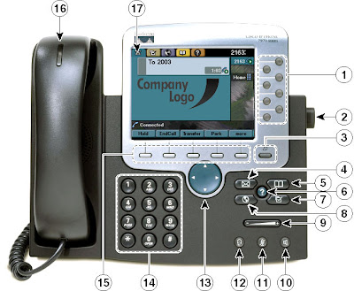
In this user guide you will find detailed information on using your Cisco IP phone. Your Cisco IP phone 7941G, 7942G, 7945G, 7961G, 7962G, 7965G, 7970 is a full-featured, multi-line telephone replacing the traditional analog phone.
  1. Line Appearance Buttons - Indicates your extension number(s).
  2. Foot Stand Button - Adjusts the angle of your phone base.
  3. Display button - Awakens the touchscreen from sleep mode or disables it for cleaning.
  4. Messages Button – Allows you to use the voice message system.
  5. Directories Button - Opens/Closes the Directories menu which allows you to see missed calls, received call, placed calls, and faculty/staff directories.
  6. Help Button – Allows you to use the Help Menu.
  7. Settings Button – Allows you to change telephone settings such as contrast and ringer sound, network configuration, and status information.
  8. Services Button - Provides access to telephone services if available.
  9. Volume Button - Increases or decreases the volume of the handset or headset, speakerphone, and the ringer volume.
  10. Speaker Button - Toggles the speaker on or off for conference calls in your office.
  11. Mute Button – Turns the mute feature on or off.
  12. Headset Button – Turns the headset on or off for those who use a headset.
  13. Navigation Button - Allows you to scroll through menus, highlight items and with the soft key activate the highlighted items.
  14. Keypad - Allows you to dial telephone numbers, enter letters, and close menu items.
  15. Soft Key Buttons - Each activates the item (soft key) listed above on a menu.
  16. Handset Light Strip - Indicates that you have an incoming call and/or a new voice message.
  17. Phone Screen – Gives you the time, date, your phone number, caller ID, and other features like redial, new call, etc.
Phone Features
Muting a Call:
     1. Press the MUTE button
             a. To end the mute feature, press the MUTE button again

Placing a Call on Hold
     1. Press the Hold soft key.
             a. To return to the call, press the Resume soft key.
         Tip: If multiple calls are on hold, Scroll with the arrows to select the desired call before you press the Resume key.

Transferring a Call to another telephone:
      1. Press the Transfer soft key
             a. This places the call on hold
      2. Dial the number to which you want to transfer the call
      3. When the number rings, press Transfer again; or when the party answers announce the call and then press Transfer
      4. Hang up if the call is accepted.
      Note: If the party refuses to accept the call, return to the original call by pressing the Resume soft key.

Transferring a Call Directly to a Voice Mailbox
       1. Press the Transfer soft key.
       2. This places the call on hold.
       3. Press the * and Dial the extension to which you want to transfer the call
       4. When the voicemail box answers, press Transfer again

Call Forwarding
   To forward your calls:
       1. Press the CFwdAll soft key.
       2. When the beep tone is heard, enter the number to which you wish to forward.
                a. Forwarding to Voicemail: Press the * and Dial the extension to which you want to transfer the call
                b. Forwarding to on-campus extension: Dial the 4-digit extension
                c. Forwarding to off-campus number: Dial 8 - 1 - area code - phone number
        3. When finished, verify Forwarded to xxxxxxxx is displayed above the LCD screen.
   To cancel call forwarding:
         1. press the CFwdAll soft key.

Placing a Conference Call
   To turn a call into a conference call:
         1. During a call, press the more option and then you should choose the Confrn soft key. (This allows you to place the party on hold while you contact others.)
         2. Place a call to another number to include others on the conference call.
         3. When the call connects, press Confrn again to add the other party to the conference call.
            Notes:
                 a. To place a conference call on hold - Press Hold.
                       i The other parties cannot talk among themselves.
                       ii To avoid disrupting the other callers, consider muting the call instead.
                              -To mute the call - Press Mute.
                 b. To place a conference call on the speakerphone - press Speaker.
                       i Press the Mute button to mute the speakerphone. The conference parties cannot hear you but you can hear them.

Cisco Conference Phone Feature
The previous diagram illustrates the Cisco Conference Call Scenario.
illustrates the IP Phone Manual Guide.
The previous manual illustrates the IP Phone Manual Guide.

Cisco IP Phone Manual 7940/7960 Models download the pdf file here

Tuesday, December 4, 2012

Standard Cisco Switch Configuration

Stand Cisco Switch Configuration
I would like to share Standard Cisco Switch Configuration in order to give readers understand best practices for Standard Cisco Switch Configuration. This concept like previos post "Standard Cisco Router Configuration"

Keep in mind again that the output you are about to see might not exactly match to the following. The output basically varies; it highly depends on your cisco switch models and features activated or used. However in general, it should look something like this.. let us see...


! Standard Cisco Switch Configuartion
!
!
service nagle
no service pad
service tcp-keepalives-in
service tcp-keepalives-out
service timestamps debug datetime msec localtime show-timezone
service timestamps log datetime msec localtime show-timezone
service password-encryption
!
hostname <<Country_Code>>SL1
!
boot-start-marker
boot-end-marker
!
!
logging buffered 128000
!
!
no aaa new-model
clock timezone PST -8
clock summer-time PDT recurring
system mtu routing 1500
vtp domain <<Facility_Code_ALL_CAPS>>
vtp mode transparent
udld aggressive
!
ip subnet-zero
no ip source-route
ip routing
ip domain-name <<Country_Code>>.domain.net
ip name-server 172.26.20.24
ip name-server 172.27.26.36
ip dhcp relay information trust-all
ip multicast-routing distributed
!
!
! DHCP SNOOPING: Prevents rogue DHCP servers from affecting PCs on the VLAN
! IMPORTANT: You MUST put 'ip dhcp snooping trust' on all Layer 2 uplinks, if any,
! for DHCP Snooping to work!
!
! IMPORTANT: Add additional VLANs here if necessary:
ip dhcp snooping vlan <<Data_VLAN_Number>>,<<Voice_VLAN_Number>>
ip dhcp snooping
!
!
errdisable recovery cause udld
!
spanning-tree mode rapid-pvst
spanning-tree portfast default ! Enable PortFast on all ports by default
spanning-tree portfast bpduguard default
spanning-tree etherchannel guard misconfig
spanning-tree extend system-id
spanning-tree backbonefast
!
vlan internal allocation policy ascending
!
!
vlan <<Data_VLAN_Number>>
 name <<Data_Subnet_CIDR_Notation>>_DATA
!
!
vlan <<Voice_VLAN_Number>>
 name <<Voice_Subnet_CIDR_Notation>>_VOICE
!
! Add additional VLANs here if necessary
!
!
vlan 999
 name Unused_Native_VLAN
!
!
ip tcp path-mtu-discovery
ip telnet source-interface Loopback0
ip ftp source-interface Loopback0
ip tftp source-interface Loopback0
!
!
interface Loopback0
 ip address <<Loopback0_Address>> 255.255.255.255
 no ip proxy-arp
!
! L3 uplink port configuration
interface GigabitEthernet1/0/1
 description Uplink to ISR
 no switchport
 ip address <<Uplink_Interface_Address>> <<Uplink_Interface_Mask>>
 no ip redirects
 no ip proxy-arp
 ip pim sparse-mode
 ip cgmp
 load-interval 30
!
!
!
interface range GigabitEthernet1/0/2-24
 auto qos voip cisco-phone
!
!
interface range GigabitEthernet1/0/2-24
 switchport access vlan <<Data_VLAN_Number>>
 switchport mode access
 switchport nonegotiate
 switchport voice vlan <<Voice_VLAN_Number>>
 no logging event link-status
 load-interval 30
 no snmp trap link-status
!
! Shutdown unused access ports
interface range GigabitEthernet1/0/25-28
 shutdown
!
! Shutdown unused uplinks
interface range TenGigabitEthernet1/0/1-2
 shutdown
!
! Shutdown VLAN 1
interface Vlan1
 no ip address
 no ip route-cache
 no ip mroute-cache
 shutdown
!
router eigrp 109
 passive-interface default
 no passive-interface GigabitEthernet1/0/1 ! Specify different port if needed
 no auto-summary
 network <<Loopback0_Address>>
 network <<Uplink_Interface_Address>>
 network <<Data_VLAN_Interface_Address>>
! Add any additional networks to EIGRP here
!
ip classless
no ip forward-protocol nd
no ip forward-protocol udp tftp
no ip forward-protocol udp nameserver
no ip forward-protocol udp domain
no ip forward-protocol udp time
no ip forward-protocol udp netbios-ns
no ip forward-protocol udp netbios-dgm
no ip forward-protocol udp tacacs
no ip http server
no ip http secure-server
ip pim rp-address 139.65.245.226 mcast-rp-sparse-wan override
ip pim spt-threshold 32
ip pim register-rate-limit 48
ip pim register-source Loopback0
ip tacacs source-interface Loopback0
banner login @
****************************************************
WARNING TO UNAUTHORIZED USERS:
This system is for use by authorized users only.
Any individual using this system, by such use,
acknowledges and consents to the right of the
company to monitor, access, use, and disclose any
information generated, received, or stored on the
systems, and waives any right of privacy or
expectation of privacy on the part of that
individual in connection with his or her use of
this system. Unauthorized and/or improper use of
this system, as delineated by corporate policies,
is not tolerated and the company may take formal
action against such individuals.
****************************************************
@
!
!
!
!
line con 0
 timeout login response 15
 access-class 20 in
 password cisco
 logging synchronous
 login
 transport preferred none
line vty 0 4
 timeout login response 15
 access-class 20 in
 password cisco
 logging synchronous
 login
 transport preferred none
line vty 5 15
 timeout login response 15
 access-class 20 in
 password cisco
 logging synchronous
 login
 transport preferred none
To download the Standard Cisco Switch Configuartion go here; Switch_Config.xlsx

Standard Cisco Router Configuration

Cisco Router Configuration
I would like to share Standard Cisco Router Configuration in order to give readers understand best practices for Standard Cisco Router Configuration.

I have seen the following issues resulting from a lack of configuration management:
  • Inability to determine user impact from network changes
  • Increased reactive support issues and lower availability
  • Increased time to resolve problems
  • Higher network costs due to unused network components

Standard Cisco Router Configuration maintaining configuration management best-practices, you can expect several benefits such as improved network availability and lower costs. These include:
  • Lower support costs due to a decrease in reactive support issues.
  • Lower network costs due to device, circuit, and user tracking tools and processes that identify unused network components.
  • Improved network availability due to a decrease in reactive support costs and improved time to resolve problems.

I recommend creating standard configurations for each device classification, such as router, LAN switch, WAN switch, Firewal or any other network devices. Global configuration commands apply to all like devices and include parameters such as service commands, IP commands, TACACS commands, vty configuration, banners, SNMP configuration, and Network Time Protocol (NTP) configuration.

Keep in mind that the output you are about to see might not exactly match to the following. The output basically varies; it highly depends on your router models and features activated or used. However in general, it should look something like this.

! Standard Cisco Router Configuartion
!
service tcp-keepalives-in
service tcp-keepalives-out
service timestamps debug datetime localtime show-timezone
service timestamps log datetime localtime show-timezone
service password-encryption
!
hostname  SAMPLE-NAME
!
!
!card type t1 0 0
!card type t1 0 1
!
!
network-clock-participate wic 0
network-clock-participate wic 1
network-clock-select 1 T1 0/1/0
network-clock-select 2 T1 0/0/0
!
!
logging buffered 128000 debugging
logging reload warnings
!
!
clock timezone CST -6
clock summer-time CDT recurring
no ip source-route
ip cef
ip telnet source-interface Loopback0
!
ip ftp source-interface Loopback0
ip tftp source-interface Loopback0
ip domain lookup source-interface Loopback0
ip domain-name  SAMPLE-NAME.domain.net
!
ip name-server 172.36.80.34
ip name-server 172.27.26.36
!
interface null0
 no ip unreachables
!
interface Loopback0
 ip address 172.30.x.xxx  255.255.255.255
 no ip proxy-arp
 ip pim sparse-mode
 ip route-cache flow
!
interface Serial0/0/0:0
 description * * * Verizon MPLS Circuit ID# <<CircuitID>> * * *
 bandwidth 1536
 load-interval 30
 ip pim sparse-mode
 encapsulation frame-relay IETF
 max-reserved-bandwidth 90
 no shut
!
interface FastEthernet0/0
 description <3750E_Hostname> <Destination_Interface>
 no switchport
 ip address <IP> <Subnet_Mask> ! Same /31 as configured on 3750E
 no ip redirects
 no ip proxy-arp
 no shut
!
no ip forward-protocol nd
no ip forward-protocol udp tftp
no ip forward-protocol udp nameserver
no ip forward-protocol udp domain
no ip forward-protocol udp time
no ip forward-protocol udp netbios-ns
no ip forward-protocol udp netbios-dgm
no ip forward-protocol udp tacacs
!
ip flow-export source Loopback0
ip flow-export version 5
ip flow-export destination xxxxxx 9995
!
no ip http server
no ip http secure-server
!
logging history size 10
logging history warnings
logging trap notifications
logging source-interface Loopback0
logging 172.36.92.124
!
access-list 10 permit 172.22.xx.xxxx
access-list 10 permit 172.27.xx.xxxx
access-list 20 permit 182.132.127.0 0.0.0.255
access-list 20 permit 188.104.13.0 0.0.0.255
access-list 30 permit 172.24.xx.xxxx
access-list 30 permit 172.27.xx.xxxx
access-list 30 permit 172.24.101.0 0.0.0.255
access-list 30 permit 172.24.172.0 0.0.0.255
access-list 40 permit 172.36.xx.xxxx
access-list 40 permit 172.38.xx.xxxx
access-list 1300 permit 172.36.xx.xxxx
access-list 1333 permit 128.113.119.128 0.0.0.63
!
snmp-server community P@55w0rd! RW 10
snmp-server community P@ssw0rd RO 30
snmp-server community mrtg RO 1300
snmp-server community VBCCrep0rting RO 1333
snmp-server ifindex persist
snmp-server trap-source Loopback0
snmp-server location <<FacilityCode>> : <<FacilityInformation>>
snmp-server contact Network Operations 089 448 9332 Option #3
snmp-server enable traps snmp authentication linkdown linkup coldstart warmstart
snmp-server enable traps envmon
snmp-server enable traps config
snmp-server enable traps entity
snmp-server host 199.103.13.208 Getronics-NMC-trap
snmp-server host 199.103.13.219 Getronics-NMC-trap
snmp-server host 172.22.88.201 Voyence  config
snmp-server host 172.22.8.201 Voyence  config
!
tacacs-server host 172.53.102.16
tacacs-server host 172.57.124.16
tacacs-server timeout 10
tacacs-server key 7 00010asdfadfaE18090C32454D
tacacs-server directed-request
!
control-plane
!
!
banner login !
****************************************************
WARNING TO UNAUTHORIZED USERS:
This system is for use by authorized users only.
Any individual using this system, by such use,
acknowledges and consents to the right of the
company to monitor, access, use, and disclose any
information generated, received, or stored on the
systems, and waives any right of privacy or
expectation of privacy on the part of that
individual in connection with his or her use of
this system. Unauthorized and/or improper use of
this system, as delineated by corporate policies,
is not tolerated and the company may take formal
action against such individuals.
****************************************************!
!
!
line con 0
 access-class 20 in
 timeout login response 15
 password cisco
 logging synchronous
 transport preferred none
 stopbits 1
line vty 0 4
 access-class 20 in
 timeout login response 15
 password cisco
 logging synchronous
 transport preferred none
 transport input telnet ssh
line vty 5 15
 access-class 20 in
 timeout login response 15
 password cisco
 logging synchronous
 transport preferred none
 transport input telnet ssh
!
scheduler allocate 20000 1000
!ntp clock-period 17179555
ntp access-group peer 40
ntp server 172.38.xxx.xx
ntp server 172.36.xxx.xxx8 prefer

To download the Standard Cisco Router Configuartion go here; Router_Config.xlsx

Saturday, October 13, 2012

Cisco Icons ~ Network Diagram Example

Cisco Icons ~ Network Diagram Example. Having been the network business a long time, I would like to pass on a few pointers that I have learned over the years. When drawing a network diagram, think about whether it makes sense to draw a logical or a physical diagram. I would say 90% of the time, a logical diagram is more useful than a physical diagram and I used these icons for drawing diagram network as standard practice. It looks PROFESSIONAL for any organization even it's SME or large size business.

I have attached an example of a logical network drawing as I did for Giant company.
Cisco Visio Stencils

Cisco Visio StencilsCisco Visio Stencils
Network Diagram Example
Cisco Visio Stencils
LAN Network Diagram
To download the Cisco conceptual Visio Stencils go here; Packet Icons Visio 1 Packet Icons Visio 2 Packet Icons Visio 3 Packet Icons Visio 4 Packet Icons Visio 5 Packet Icons Visio 6 Visio Stencils

Saturday, September 22, 2012

Network Diagram Templates

Here are a few simple tips to help you create quality, professional-looking network diagrams.

Use Multiple Pages
The number one mistake in many network diagrams is an attempt to convey too much information on one page. Visio allows use of multiple pages just like an Excel workbook with many worksheets, so consider using multiple drawing sheets for different purposes.

Make Use of Border Templates
A border template can make your life a little easier by providing a way to track changes to your diagrams. In your template include sections for author name, version number, date, page number, and any other fields that will be useful. Most of the fields can automatically update themselves - more information on that can be found on the Microsoft website here.

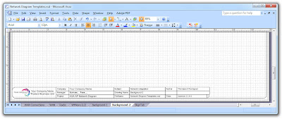
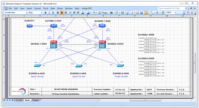
For example, if you want a background page that displays your company logo, or a title block that contains fields such as the creation date of a drawing, subject, Author, Drawing name, Filename, Manager, create these items and assign them to the foreground page. Let us see the example of what are on the visio after creating the Network Diagram Templates:
Network Diagram Templates Background 
Network Diagram Templates Background Network Diagram Templates BackgroundTemplates Background Insert Page
Diagram Templates Background

Friday, April 6, 2012

Cisco WLAN design

      With most WLAN designs, security is the first capability folks worry about. Fortunately, WLAN technology contains robust security features with viable authentication and encryption mechanisms. A security solution can be designed in a variety of ways, however. This tip provides some best practices for designing effective security architectures.


       We will cover specific design aspects of the Cisco WLAN solution utilizing controller-based architectures. These design best practices have been developed over the course of multiple design initiatives with the Cisco solution and primarily from lessons learned from deploying the Cisco solution. Most of the information is related to the Cisco solution, but some of the lessons learned and best practices relate to the process behind deploying the designs.

User considerations
       In most organizations, the user community dictates the security architecture. It is not a one-size-fits-all approach. The recommended approach is to identify the user communities that will utilize the WLAN system and design the security accordingly.

As a foundation, the following user communities are a good place to start:
  • Employees/visiting employees -- require access to corporate applications and need those applications to be secure
  • Contractors -- on site temporarily, but for an extended period of time; require access to some corporate applications (other than just Internet)
  • Guests -- need access to Internet only


Tuesday, April 3, 2012

Multi-Protocol Label Switching (MPLS)

   This article identifies Multi-Protocol Label Switching (MPLS) technology components, describes their functionality, and illustrates the value they provide in Service Provider environments.

       MPLS was initially targeted for Service Provider customers; however, Enterprises have begun to show interest in deploying this technology. This document can apply to large Enterprise customer whose networks resemble Service Provider networks in the following areas:
  • Size of the network
  • Offer "internal services" to different departments within the Enterprise
   MPLS compliments IP technology. It is designed to leverage the intelligence associated with IP Routing, and the Switching paradigm associated with Asynchronous Transfer Mode (ATM). MPLS consists of a Control Plane and a Forwarding Plane. The Control Plane builds what is called a "Forwarding Table," while the Forwarding Plane forwards packets to the appropriate interface (based on the Forwarding Table).
   The efficient design of MPLS uses Labels to encapsulate IP packets. A Forwarding Table lists Label Values, which are each associated with determining the outgoing interface for every network prefix. Cisco IOS Software supports two signaling mechanisms to distribute labels: Label Distribution Protocol (LDP) and Resource Reservation Protocol/Traffic Engineering (RSVP / TE).

MPLS comprises the following major components:
  1.  MPLS Virtual Private Networks (VPNs)—provides MPLS-enabled IP networks for Layer 3 and Layer 2 connectivity. Includes two major components:    1.  Layer 3 VPNs—based on Border Gateway Patrol    2.  Layer 2 VPNs—Any Transport over MPLS (AToM)
  2. MPLS Traffic Engineering (TE)— provides an increased utilization of network bandwidth inventory and for protection services
  3. MPLS Quality of Service (QoS)— buildings upon existing IP QoS mechanisms, and provides preferential treatment to certain types of traffic, based on a QoS attribute (i.e., MPLS EXP).
MPLS VPNs (Layer 3 VPNs)
   Layer 3 VPNs or BGP VPNs have been the most widely deployed MPLS technology. They use Virtual Routing instances to create a separate routing table for each subscriber, and use BGP to establish peering relations and signal the VPN-associated labels with each of the corresponding Provider Edge (PE) routers. This results in a highly scalable implementation, because core (P) routers have no information about the VPNs.

   BGP VPNs are useful when subscribers want Layer 3 connectivity, and would prefer to offload their routing overhead to a Service Provider. This ensures that a variety of Layer 2 interfaces can be used on either side of a VPN. For example, Site A can use an Ethernet interface, while Site B uses an ATM interface; however, Sites A and B are part of a single VPN.

It is relatively simple to implement multiple topologies with router filtering, including a Hub & Spoke or Full Mesh:
  • Hub and Spoke—central site is configured to "learn" all the routes from the remote sites, while the remote sites are restricted to "learn" routes only from the central site.
  • Full Mesh topologies would result in all the sites having the ability to "learn" or import routes from every other site.
    Layer 3 VPNs have been deployed in networks that have as many as—seven hundred PE routers. Service Providers are currently providing up to five hundred VPNs, with each VPN containing as many as one thousand sites. A wide variety of routing protocols are available deploy on the subscriber access link (i.e. CE to PE link). These include Static Routes, BGP, RIP and Open Shortest Path First (OSPF). Most VPNs have been deployed with Static Routes, followed by BGP Routing.

   Layer 3 VPNs offer advanced capabilities, including Inter-AS and Carrier Supporting Carrier (CSC). These provide hierarchical VPNs, allowing a Service Provider to provide connectivity across multiple administrative networks. Currently, initial deployments of such functionality are becoming more widespread.
Download MPLS FLASH PRESENTATION here Full Mesh, Point to Point

Sunday, April 1, 2012

Cisco Catalyst 6500 Series Supervisor Engine 720

The Cisco® Catalyst® 6500 Series Supervisor Engine 720 is a family of Supervisor Engine(s) designed to deliver scalable performance and rich set of IP features in hardware. Its hardware-based feature set enables applications such as traditional IP forwarding, Layer 2 and Layer 3 Multiprotocol Label Switching (MPLS) VPNs, Ethernet over MPLS (EoMPLS) with quality of service (QoS) and security features. The Supervisor engine 720 integrates a high-performance 720 Gbps crossbar switch fabric with a forwarding engine in a single module, delivering 40 Gbps of switching capacity per slot (enabling 4-port 10GE and 48-port 10/100/1000 density line cards). With hardware-enabled forwarding for IPv4, IPv6 and MPLS, the system performance is capable of 400 Mpps for IPv4, 200 Mpps for IPv6 traffic, with features and 1024 VRFs each populated with up to 700 routes/VRF for MPLS


NIC Teaming and Cisco Switch Config

Server Configuration
       Server Access port configuration 
Server access ports typically fall into three categories:
  1. Normal servers which require simple gigabit connectivity with fail on fault cards (what HP calls Network Fault Tolerance – NFT)
  2. High bandwidth servers which require two gigabit throughput using aggregation
  3. VMWare servers which require special configuration 
Some initial thoughts
       Nowadays auto-negotiation of speed and duplex works well with server gigabit interfaces so do not try and set the speed or duplex manually. One reason is auto-negotiation enables the cable-tester built into some gigabit Ethernet modules to function.
For example:
switch#test cable-diagnostics tdr interface gi1/2/1
TDR test started on interface Gi1/2/1
A TDR test can take a few seconds to run on an interface
Use 'show cable-diagnostics tdr' to read the TDR results.
switch#show cable-diagnostics tdr interface gi1/2/1
TDR test last run on: August 06 13:58:00
Interface Speed     Pair Cable length Distance to fault   Channel Pair status
             --------- ----- ---- ------------------- ------------------- ------- ------------
Gi1/2/1   1000  1-2  0    +/- 6  m       N/A                Pair B  Terminated 
                       3-6  0    +/- 6  m       N/A                 Pair A  Terminated 
                       4-5  0    +/- 6  m       N/A                 Pair D  Terminated 
                       7-8  0    +/- 6  m       N/A                 Pair C  Terminated 


       If a server comes in at 100 Mbps and the server is also set to auto/auto, it is likely that there is a cable fault (gigabit requires all pairs to be terminated where 100 Base-T does not).
       Access ports should also be set to spanning-tree portfast as per established practice.
       Port-security is also worth mentioning as it is NOT compatible with dual-homed servers using HP’s network teaming software. Any cable fault on NIC 1 results in the MAC address shifting over to NIC 2’s port and the switch sees this as a security violation, blocks traffic and generates this syslog message.

Normal ServersSwitch Configuration

interface <interface name>
 switchport
 !Set an access VLAN
 switchport access vlan <###>
 !Force access mode
 switchport mode access
 !Set an acceptable broadcast storm level
 storm-control broadcast level 0.10
 !Port-security is not compatible with dual-homed servers
 no switchport port-security
 no switchport port-security maximum
 no switchport port-security violation restrict
 spanning-tree portfast
end

Server configuration
       The default configuration on HP servers for a teaming interface is Type: Automatic and Transmit: Automatic. This configuration will, on non-etherchannel switch ports, default to Transmit Load Balancing with Fault Tolerance (TLB). One NIC will transmit and receive traffic whilst the other will only transmit.
       From a network point of view this makes troubleshooting difficult, as transmit traffic is spread over two NICs with two MAC addresses and receive traffic is directed to just one NIC depending on what NIC responds to ARP requests. 
Our PREFERRED configuration is to use either: 
NFT Teaming Configuration
NFT Teaming with preference configuration
       Two servers that are known to exchange a lot of traffic with each other but do not use Etherchannel should use NFT with preference and ensure that the active NICs on both servers go to the same switch.

High Bandwidth Servers

Switch Configuration

Note: most settings MUST match between all ports in the same Etherchannel group (e.g. storm-control; access mode; and vlan).
interface <interface name> switchport
 !Set an access VLAN switchport access vlan <###>
 !Force access mode switchport mode access
 !Set an acceptable broadcast storm level storm-control broadcast level 0.10
 !port-security is not compatible with channelling  no switchport port-security
 no switchport port-security maximum
 no switchport port-security violation restrict
 !Force LACP & enable as passive mode channel-protocol lacp
 channel-group <#> mode passive
 spanning-tree portfast
 !Force flowcontrol off to stop any channelling issues
 !Intel cards default to no flow control; HP on-board default to on

 flowcontrol receive off
 flowcontrol send off
end


Sample output showing two links being aggregated:
switch#show int po100 etherchannel
Port-channel100   (Primary aggregator)

Age of the Port-channel   = 1d:01h:38m:34s
Logical slot/port   = 14/4          Number of ports = 2
HotStandBy port = null
Port state          = Port-channel Ag-Inuse
Protocol            =   LACP
Fast-switchover     = disabled

Ports in the Port-channel:

Index Load Port    EC state    No of bits
------+------+------+------------------+-----------
  1     FF   Gi1/2/1  Passive    8
  0     FF   Gi2/2/1  Passive    8

Time since last port bundled:    0d:00h:00m:05s    Gi1/2/1
Time since last port Un-bundled: 0d:00h:00m:33s    Gi1/2/1
Server configuration
       The default configuration on HP servers for a teaming interface is Type: Automatic and Transmit: Automatic. This configuration will attempt to negotiate an etherchannel using LACP and if this fails to use Transmit Load Balancing (TLB). As long as the port-channel and its corresponding physical interfaces are configured correctly the default configuration seems to work well. Although TLB is not our preferred failback connection type, there does not appear to be a way to enable channelling with NFT fallback.

Default Teaming Configuration
Successful LACP negotiation
Unsuccessful LACP negotiation
Other features such as duplex/speed and flowcontrol are best left at defaults.

Jumbo Frames
       Jumbo frames may improve performance of some applications, but no testing has been done at the time of writing to verify whether they introduce problems either locally or to remote users on a 1500 byte MTU WAN connection or whether they do indeed improve performance as much as some would believe. http://www.nanog.org/mtg-0802/scholl.html may be useful reading.
       Jumbo frames are also incompatible with HP’s TCP Offload Engine (TOE) NICs so jumbo frames may suffer from reduced throughput. More testing and investigation will be required before coming to any firm conclusions or recommendations. Therefore at the current time, our recommendation for host access ports is to use a standard 1500 byte MTU / 1518 byte frame size.
       However, since every trunk link on a LAN has to support the highest MTU, it is worth building the LAN’s trunk links to support a high MTU even if the access ports still run at 1514 bytes. This leaves the option open for later adoption at the host layer and allows easy adoption of some devices that require a high MTU such as Fibrechannel over IP.