Cisco Routers

Cisco routers provide access to applications and services, and integrate technologies

IP Phone - Cisco

IP phone takes full advantage of converged voice and data networks, while retaining the convenience and user-friendliness you expect from a business phone...

WAN - Cisco Systems

Transform your WAN to deliver high-performance, highly secure, and reliable services to unite campus, data center, and branch networks.

EtherChannel - Cisco Systems

EtherChannel provides incremental trunk speeds between Fast Ethernet, Gigabit Ethernet, and 10 Gigabit Ethernet. EtherChannel combines multiple Fast ...

Looking Toward the Future - Cisco Systems

Looking Toward the Future by Vint Cerf. The Internet Corporation for Assigned Names and Numbers (ICANN) was formed 9 years ago....

Pages

Saturday, November 16, 2013

How to find specific mac address or IP address in a Cisco Switch port

Trick and tip for network admin you should know when you work on enterprice switch. These commands will help you to work faster. If you know the IP address of the device then try to ping it from within the switch. If the device is pingable, then do a simple sh ip arp command. This command will show the MAC address of the device. 

TB-CS-4506#
TB-CS-4506#ping 142.30.15.254                                                        ## Step 1
Type escape sequence to abort.
Sending 5, 100-byte ICMP Echos to 142.30.15.254, timeout is 2 seconds:
!!!!!
Success rate is 100 percent (5/5), round-trip min/avg/max = 1/4/9 ms

TB-CS-4506#
TB-CS-4506#sh ip arp 142.30.15.254                                                ## Step 2
Protocol  Address          Age (min)  Hardware Addr   Type   Interface
Internet  142.30.15.254         140   18ef.63dc.aacd  ARPA   Vlan20

Then, do the show mac-address command on the switch. This will show the interface (or IP) to which it is connected to a port or through which it is learned.

TB-CS-4506# 
TB-CS-4506#sh mac address-table address 18ef.63dc.aacd         ## Step 3
          Mac Address Table
-------------------------------------------
Vlan    Mac Address       Type        Ports
----    -----------       --------    -----
  20    18ef.63dc.aacd    DYNAMIC     Gi2/0/5
Total Mac Addresses for this criterion: 1
TB-CS-4506#

This indicate the the device is connected to port GigabitEthernet2/0/5. There you can find the device.

Cisco Switch Command

Note: You can use the below command to check the ip address of devices on different subnet
"ping ip" then "show ip arp | include <mac address>" or "show cdp neighbors detail | begin <mac address>"
 

How to configure SNMP cisco and basic commands for Snmpwalk

This article will guide your through the steps to enable SNMP in Cisco Routers and Switches including how to apply security as the configuration of the underlying devices. This is to make the devices more secure same as international companies worldwide practice.

Cisco SNMP Agent
 
Here's an example:
  1. Telnet to the switch/router
    C:\Users\LAX>telnet THHQCE7-3845
  2. Enter the Enable mode
    THHQCE7-3845> enable
    Password:
    THHQCE7-3845#
  3. Enter Config Mode
    THHQCE7-3845# configure terminal
  4. Use the command below to add a Read-Only an Read write community string
    THHQCE7-3845(config)# snmp-server community 14all3$$ RO
    THHQCE7-3845(config)# snmp-server community gds4chv1 RW
Configuration Examples for snmp-server setting:
   snmp-server community 14all3$$ RO 30
   snmp-server community gds4chv1 RW 10
   snmp-server community mrtg RO 1300
   snmp-server community VBCCrep0rting RO 1333
   snmp-server ifindex persist
   snmp-server trap-source Loopback0
   snmp-server location THHQCE7-3845: Facility-Code THHQ, Offshore (Thailand) Ltd, Bangkok7th floor, Building BB, 123 Vibhavadi Road, Jatujak, Bangkok 10900
   snmp-server contact network operations 66-6428 xxxx
   snmp-server enable traps tty
   snmp-server enable traps config
   snmp-server host 172.20.71.201 Voyence  config
   snmp-server host 172.20.3.35 Voyence  config
   snmp-server host 172.20.71.201 config
   snmp-server host 172.20.9.201 config

Next, I highly recommend to configure SNMP in order to make it secure. If you want to secure the communication between network monitoring tool (WhatsUp, Solarwinds, Nagios) and the switches/routers you'll have to use SNMPv3.

ACL SNMP setting example;
   !<----- ACL 10 for Read Write, ACL 30 for Read Only
   !
   ! ACL 10 – SNMP READ WRITE
   !
   no access-list 10
   access-list 10 permit 172.27.124.18 log
   access-list 10 permit 136.171.124.18 log
   access-list 10 permit 172.20.71.200 log
   access-list 10 permit 172.20.9.200 log
   access-list 10 permit 172.20.50.21 log
   access-list 10 permit 172.20.46.70 log
   access-list 10 deny any log
   !
   !
   ! ACL 30 – SNMP READ ONLY
   !
   no access-list 30
   access-list 30 permit 172.20.46.89 log
   access-list 30 permit 172.20.46.114 log
   access-list 30 permit 172.20.50.22 log
   access-list 30 permit 172.20.32.5 log
   access-list 30 permit 172.20.46.5 log
   access-list 30 permit 172.20.46.6 log
   access-list 30 permit 172.20.46.8  log
   access-list 30 deny any log
   !


Testing:
   To test the new configuration use snmpwalk on your linux server running your network monitoring tools

   [root@ARNAG libexec]#snmpwalk -v 2c -c COMMUNITYSTRING IPADDRESS
   [root@ARNAG libexec]# snmpwalk -v2c -c Savvi148 172.20.1.35
   SNMPv2-MIB::sysDescr.0 = STRING: Cisco IOS Software, C2960S Software (C2960S-         UNIVERSALK9-M), Version 12.2(55)SE7, RELEASE SOFTWARE (fc1)
   Technical Support: http://www.cisco.com/techsupport
   Copyright (c) 1986-2013 by Cisco Systems, Inc.
   Compiled Mon 28-Jan-13 10:28 by prod_rel_team
   SNMPv2-MIB::sysObjectID.0 = OID: SNMPv2-SMI::enterprises.9.1.1208
   DISMAN-EVENT-MIB::sysUpTimeInstance = Timeticks: (209528058) 24 days, 6:01:20.58
   SNMPv2-MIB::sysContact.0 = STRING:
   SNMPv2-MIB::sysName.0 = STRING: THHQSL2-2960S
   SNMPv2-MIB::sysLocation.0 = STRING:
   SNMPv2-MIB::sysServices.0 = INTEGER: 6
   SNMPv2-MIB::sysORLastChange.0 = Timeticks: (0) 0:00:00.00
   SNMPv2-MIB::sysORID.1 = OID: SNMPv2-SMI::enterprises.9.7.129
   SNMPv2-MIB::sysORID.2 = OID: SNMPv2-SMI::enterprises.9.7.115
   SNMPv2-MIB::sysORID.3 = OID: SNMPv2-SMI::enterprises.9.7.265
   SNMPv2-MIB::sysORID.4 = OID: SNMPv2-SMI::enterprises.9.7.112
   SNMPv2-MIB::sysORID.5 = OID: SNMPv2-SMI::enterprises.9.7.106
   SNMPv2-MIB::sysORID.6 = OID: SNMPv2-SMI::enterprises.9.7.47
   SNMPv2-MIB::sysORID.7 = OID: SNMPv2-SMI::enterprises.9.7.122
   SNMPv2-MIB::sysORID.8 = OID: SNMPv2-SMI::enterprises.9.7.135
   SNMPv2-MIB::sysORID.9 = OID: SNMPv2-SMI::enterprises.9.7.43
   SNMPv2-MIB::sysORID.10 = OID: SNMPv2-SMI::enterprises.9.7.37

These are the command to check Input/Output Discard and Input/Outpu Errors :
   [root@ARNAG libexec]#snmpwalk -Ofn -v 1 -c Savvi148 172.30.1.20 1.3.6.1.2.1.2.2.1.19
         "ifOutDiscards"  "1.3.6.1.2.1.2.2.1.19"
   [root@ARNAG libexec]#snmpwalk -Ofn -v 1 -c Savvi148 172.30.1.20 1.3.6.1.2.1.2.2.1.13
         "ifInDiscards"  "1.3.6.1.2.1.2.2.1.13"
   [root@ARNAG libexec]#snmpwalk -v2c -c Savvi148 172.20.1.20 .iso.org.dod.internet.mgmt.mib-2.interfaces.ifTable.ifEntry
            1 . 3  .  6  .    1      .   2    .   1     .     2        .      2    .    1     . 13
         .iso.org.dod.internet.mgmt.mib-2.interfaces.ifTable.ifEntry.ifInDiscards
         .iso.org.dod.internet.mgmt.mib-2.interfaces.ifTable.ifEntry.ifInErrors
         .iso.org.dod.internet.mgmt.mib-2.interfaces.ifTable.ifEntry.ifOutDiscards
         .iso.org.dod.internet.mgmt.mib-2.interfaces.ifTable.ifEntry.ifOutErrors

Cisco SNMP


Saturday, June 8, 2013

Configure Netflow For Cisco Router Switch IOS - Example


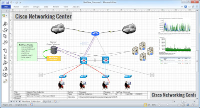
What we will get benefit when we enable netflow feature are real-time monitoring of host behaviors and traffic analysis to identify threats, extensive network performance reports including top talkers, interface utilization, exporter tracking, etc. I have screenshot for your carification.
NetFlow Collection on Cisco IOS
Below is how to set up step by step on Cisco router or Cisco switch;
  • Enabling NetFlow
    Enter global configuration mode on Cisco router or Cisco switch, and issue the following commands for each interface on which you want to enable NetFlow:
         #interface {interface} {interface_number}
         #ip route-cache flow
  • Enabling the exports of these flows
    Enter global configuration mode on Cisco router or Cisco switch, and issue the following commands by use the IP address of your NetFlow Collector and configured listening port. UDP port 9995 is used for example.
         # ip flow-export version 5
         # ip flow-export destination <ip_address> 9995
         # ip flow-export source Loopback0
  • Turning off NetFlow
    Issue the following commands in global configuration mode to stop exporting NetFlow data:
         #interface {interface} {interface_number}
         #no ip route-cache flow
    This will disable NetFlow export on the specified interface. Repeat the commands for each interface on which you need to disable NetFlow.
  • Diagnosis
    In enable mode you can see current NetFlow configuration and state by looking at the output from
         #sh ip flow export Shows the current NetFlow configuration
         #show ip cache flow and sh ip cache verbose flow These commands summarize the active flows and give an indication of how much NetFlow data the device is exporting

    Note: When access lists are used, all cisco routers or cisco switch must log failed network access attempts.
packet netflow analyzer
A Sample Device Configuration
The following is a set of commands issued on a router to enable NetFlow version 5
!
interface Loopback0
 ip address 172.30.203.253 255.255.255.255
 no ip redirects
 no ip proxy-arp
 ip route-cache flow
 no ip mroute-cache
!
!
interface FastEthernet0/1/0
 description LINE:USHQ-VzBPIP,SPEED:8000000,GOLDCAR:256k,DEST:VzB_PERouter
 bandwidth 8000
 ip address 172.30.0.86 255.255.255.252
 no ip redirects
 no ip unreachables
 no ip proxy-arp
 no ip route-cache cef
 ip route-cache flow
 no ip mroute-cache
 load-interval 30
 duplex full
 speed 100
 no mop enabled
!
interface FastEthernet0/1/1
 description Local Network segment for THHQ
 ip address 172.30.0.86 255.255.255.252
 no ip redirects
 no ip unreachables
 no ip proxy-arp
 no ip route-cache cef
 no ip route-cache flow
 duplex auto
 speed auto
 no cdp enable
 no mop enabled
!
!
ip flow-export source Loopback0
ip flow-export version 5
ip flow-export destination 172.30.46.195 9995
ip flow-export destination 172.30.46.71 2055
!
!
access-list 30 permit 172.30.46.195
access-list 30 permit 172.30.46.71
access-list 30 deny   any log
!
SolarWinds NetFlow Analyzer
 

Monday, June 3, 2013

ACS group tacacs+ and RADIUS-LOGIN configuration example

TACACS+ consists of three services: authentication, authorization, and accounting. Authentication is the action of determining who the user is and whether he or she is allowed access to the switch. Authorization is the action of determining what the user is allowed to do on the system. Accounting is the action of collecting data related to resource usage and now TACACS+ is in the part of the new CCNA Security certification exam.

Below configuration were created to provide you a basic understanding of AAA; that of which is commonly used in production networks for authentication, authorization and accounting.

Step 1: Create a backup user account
INHQRL2-3845(config)# dcth privilege 15 password datakrub!

Step 2: Enabling AAA
INHQRL2-3845(config)# aaa new-model

Step 3: Configuring the TACACS+ servers
INHQRL2-3845(config)# tacacs-server host 10.1.50.101 key cisco12345

Step 4: Define the AAA method lists
INHQRL2-3845(config)# aaa authentication login default group tacacs+ local
INHQRL2-3845(config)# aaa authorization exec default group tacacs+ local

Step 5: Enforcing AAA authentication on terminal lines
INHQRL2-3845(config)# line console 0
INHQRL2-3845(config-line)# login authentication default
INHQRL2-3845(config)# line vty 0 15
INHQRL2-3845(config-line)# login authentication default


The following snipped are from the TACACS+ authentication configuration on cisco devices.
Example 1: Group tacacs+ enable
!
username dcth privilege 15 password datakrub!
!
enable secret g8:ugvl 
!
ip telnet source-interface lo 0
!
line con 0
password dcth!
login local
!
line vty 0 4
password dcth!
login local
!
!
!
aaa new-model
!
aaa authentication login vty group tacacs+ local
aaa authorization exec vty group tacacs+ none
aaa authorization commands 0 vty group tacacs+ local
aaa authorization commands 1 vty group tacacs+ local
aaa authorization commands 7 vty group tacacs+ local
aaa authorization commands 15 vty group tacacs+ local
!
aaa authentication login console group tacacs+ local
aaa authorization exec console group tacacs+ none
aaa authorization commands 1 console group tacacs+ local
aaa authorization commands 7 console group tacacs+ local
aaa authorization commands 15 console group tacacs+ local
!
aaa authentication enable default group tacacs+ enable
!
aaa accounting exec vty start-stop group tacacs+
aaa accounting commands 1 vty start-stop group tacacs+
aaa accounting commands 7 vty start-stop group tacacs+
aaa accounting commands 15 vty start-stop group tacacs+
aaa accounting exec console start-stop group tacacs+
aaa accounting commands 1 console start-stop group tacacs+
aaa accounting commands 7 console start-stop group tacacs+
aaa accounting commands 15 console start-stop group tacacs+
!
aaa authorization console
aaa authorization config-commands
!
!
!
ip tacacs source-interface Loopback 0
!
!
tacacs-server host 10.1.50.101
tacacs-server key cisco12345
!
!
!
!
!
line con 0
 authorization exec console
 authorization command 1 console
 authorization command 7 console
 authorization command 15 console
 accounting commands 1 console
 accounting commands 7 console
 accounting commands 15 console
 accounting exec console
 logging synchronous
 login authentication console
line vty 0 4
 authorization commands 1 vty
 authorization commands 7 vty
 authorization commands 15 vty
 authorization exec vty
 accounting commands 1 vty
 accounting commands 7 vty
 accounting commands 15 vty
 accounting exec vty
 logging synchronous
 login authentication vty
!
!
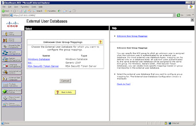
Cisco Secure ACS and Active Directory
 
RADIUS and TACACS+ server
Example 2: ACS group tacacs+  and RADIUS-LOGIN group enable
!
enable secret 5 $1$azKE$exucFBdjapkq2aspUIS7M0
!
aaa new-model
!
aaa authentication login ACS group tacacs+ enable
aaa authentication login RADIUS-LOGIN group radius
aaa authentication enable default group tacacs+ enable
aaa authentication ppp RADIUS-LOGIN group radius
aaa authorization console
aaa authorization config-commands
aaa authorization exec ACS group tacacs+ if-authenticated
aaa authorization commands 0 ACS group tacacs+ if-authenticated
aaa authorization commands 1 ACS group tacacs+ if-authenticated
aaa authorization commands 15 ACS group tacacs+ if-authenticated
aaa accounting update newinfo
aaa accounting exec ACS start-stop group tacacs+
aaa accounting commands 0 ACS start-stop group tacacs+
aaa accounting commands 1 ACS start-stop group tacacs+
aaa accounting commands 15 ACS start-stop group tacacs+
aaa accounting connection ACS start-stop group tacacs+
!
ip ssh source-interface Loopback0
!
ip tacacs source-interface Loopback0
!
access-list 20 permit 156.32.0.0 0.1.255.255
access-list 20 permit 156.34.0.0 0.7.255.255
access-list 20 permit 156.42.0.0 0.7.255.255
access-list 20 permit 156.50.0.0 0.3.255.255
access-list 20 permit 156.54.0.0 0.1.255.255
access-list 20 permit 156.56.0.0 0.0.255.255
access-list 20 permit 146.171.0.0 0.0.255.255
access-list 20 permit 149.65.0.0 0.0.255.255
access-list 20 permit 189.103.13.0 0.0.0.255
access-list 20 permit 156.52.71.192 0.0.0.63
access-list 20 permit 156.52.9.192 0.0.0.63
access-list 20 deny   any log
!
!
tacacs-server host 156.52.197.26
tacacs-server host 156.52.8.16
tacacs-server timeout 10
tacacs-server directed-request
tacacs-server key 7 06031D344F4B1GG606041B08
!
!
line con 0
 access-class 20 in
 timeout login response 15
 password 7 040A3757062A1F7459160B1956035C57
 logging synchronous
 transport preferred none
 stopbits 1
line vty 0 4
 access-class 20 in
 timeout login response 15
 password 7 124839461B005F3E7A242A26773D7240
logging synchronous
 transport preferred none
 transport input telnet
!
!
**********************************************************************************************
WARNING TO UNAUTHORIZED USERS:
This system is for use by authorized users only. Any individual using this system,
by such use, acknowledges and consents to the right of the company to monitor,
access, use, and disclose anyinformation generated, received, or stored on the
systems, and waives any right of privacy or expectation of privacy on the part of
that individual in connection with his or her use of this system.
**********************************************************************************************
Username: boylaser
Enter PASSCODE: *


You could now configure TACACS+ server for system authentication

Sunday, June 2, 2013

Show interface link Catalyst 4500, 6500, 3750, 2960

The "show interfaces link" command is supported in Catalyst 4500 Series only, this command displays how long a cable has been disconnected from an interface and you can add the modifier known like “include” with the keyword “weeks” #sh int link | inc week, you will have more ports released for future connection..

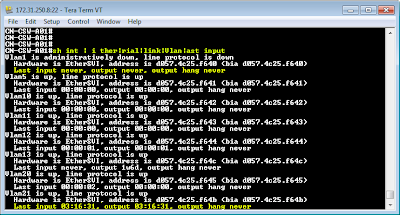
As we know this command is not supported in Catalyst 6500 series, 3750 series and 2960 series but you can use the "sh int | i ther|rial|link|Vlan|ast input" and "sh int gi 0/1 | inc ast input" command that will display the down time for each port instead. Here are an example:

Show interface link 6500, 3750, 2960
CN-CSW-A01#sh int | i ther|rial|link|Vlan|ast input
......
GigabitEthernet1/0/29 is up, line protocol is up (connected)
  Hardware is Gigabit Ethernet, address is d057.4c25.f61d (bia d057.4c25.f61d)
  Last input never, output 00:00:01, output hang never
GigabitEthernet1/0/30 is up, line protocol is up (connected)
  Hardware is Gigabit Ethernet, address is d057.4c25.f61e (bia d057.4c25.f61e)
  Last input never, output 00:00:00, output hang never
GigabitEthernet1/0/31 is up, line protocol is up (connected)
  Hardware is Gigabit Ethernet, address is d057.4c25.f61f (bia d057.4c25.f61f)
  Last input never, output 00:00:04, output hang never
GigabitEthernet1/0/32 is up, line protocol is up (connected)
  Hardware is Gigabit Ethernet, address is d057.4c25.f620 (bia d057.4c25.f620)
  Last input never, output 00:00:04, output hang never
GigabitEthernet1/0/33 is up, line protocol is up (connected)
  Hardware is Gigabit Ethernet, address is d057.4c25.f621 (bia d057.4c25.f621)
  Last input never, output 00:00:09, output hang never
GigabitEthernet1/0/34 is up, line protocol is up (connected)
  Hardware is Gigabit Ethernet, address is d057.4c25.f622 (bia d057.4c25.f622)
  Last input never, output 00:00:09, output hang never
GigabitEthernet1/0/35 is up, line protocol is up (connected)
  Hardware is Gigabit Ethernet, address is d057.4c25.f623 (bia d057.4c25.f623)
  Last input 00:00:04, output 00:00:00, output hang never
GigabitEthernet1/0/36 is up, line protocol is up (connected)
  Hardware is Gigabit Ethernet, address is d057.4c25.f624 (bia d057.4c25.f624)
  Last input 00:00:22, output 00:00:00, output hang never
GigabitEthernet1/0/37 is up, line protocol is up (connected)
  Hardware is Gigabit Ethernet, address is d057.4c25.f625 (bia d057.4c25.f625)
  Last input 00:00:18, output 00:00:00, output hang never

Command sh int gi 0/1 | inc ast input
CN-ASW-B02# sh int gi 0/1 | inc ast input
  Last input 18w3d, output 18w3d, output hang never
CN-ASW-B02# sh int gi 0/2 | inc ast input
  Last input 19w4d, output 19w4d, output hang never
CN-ASW-B02# sh int gi 0/3 | inc ast input
  Last input 8w0d, output 7w6d, output hang never
CN-ASW-B02# sh int gi 0/4 | inc ast input
  Last input 00:00:29, output 00:00:05, output hang never
CN-ASW-B02# sh int gi 0/5 | inc ast input
  Last input 18w3d, output 18w3d, output hang never
CN-ASW-B02# sh int gi 0/6 | inc ast input
  Last input 12w0d, output 12w0d, output hang never
CN-ASW-B02# sh int gi 0/7 | inc ast input
  Last input 1d01h, output 1d01h, output hang never
CN-ASW-B02# sh int gi 0/8 | inc ast input
  Last input 00:00:35, output 00:00:04, output hang never

You could now do a show show interface link to see the the down time for each port, a port was last used and plan for future connection.

Friday, February 1, 2013

How to setup Login Banner on Cisco Devices(Router, Switch, ASA) ~ Example

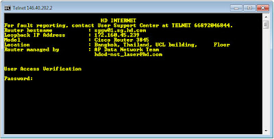
Before being given the opportunity to logon to any Company Cisco network devices, users must be presented with a Login Banner that states whom should be using the system and that monitoring is possible.... it prompt when someone will login into the cisco devices by Telnet and Console that also could be a message for unauthorize accessing of your cisco router, switch and firewall as a notice. So I would like to share How to setup Login Banner, EXEC & MOTD Banner(s) on Cisco Devices(Router, Switch, ASA) including the example...

Banner Typical Use
  • Message of the Day (MOTD)  Show before the login prompt. The MOTD banner is displayed on all terminals and is useful for sending messages that affect all users and for temporary messages that may change from time to time, such as “Router1 down for maintenance at midnight.”
  • Login  Show before the login prompt but after the MOTD banner. For permanent messages such as “Unauthorized Access Prohibited.”
  • Exec  Shown after the login prompt. Used to supply information that should be hidden from unauthorized users.
Let's see how to configure a login benner on Cisco Devices(Router, Switch, ASA)
Switch(config)#banner login {char} {banner text} {char}
For example
Switch(config)#banner login #
Enter TEXT message. End with the character '#'.
*****************************************************************************
WARNING TO UNAUTHORIZED USERS:
This system is for use by authorized users only. Any individual using this system, by such use,
acknowledges and consents to the right of the company to monitor, access, use, and disclose any
information generated, received, or stored on the systems...........
*****************************************************************************
#
Switch(config)#
This can be also used variables like:
|==========================================================|
 Hostname $(hostname)
 Domain $(domain)
 Line $(line)
|==========================================================|

Below are the example display the standard corporate login banner before a user attempts to log into a cisco switch, router and firewall.
Banner Login Cisco
Login, EXEC & MOTD Banner
Here are a cisco router, switch, ASA, etc.. login banner example, you can download and apply to your cisco devices and/or any other network devices:WARNING.txt, Network Security Team.txt, UNAUTHORIZED USERS.txt, Crimes.txt ...

Related Configuration Commands:
   - Standard Cisco Router Configuration
   - Standard Cisco Switch Configuration
   - Spanning Tree Protocol (STP) - Cisco Systems

Monday, January 21, 2013

First Hop Redundancy protocol comparison (HSRP,VRRP,GLBP) with the diagram

This time, I will talk about a First Hop Redundancy Protocol (FHRP) that i have already made it as a short note. I could pass CISCO exam because of this so i just would like to share. You can then compare your solution with a suggested solution and apply with your business. Accordingly, you can take advantage of a first-hop redundancy protocol. ... HSRP, VRRP and GLBP are the main three first hop redundancy protocols.

The following table provides difference HSRP, VRRP and GLBP protocols.
Property   HSRP VRRP GLBP
Administrative Distances Hot Standby Router Protocol (HSRP) Virtual Router Redundancy Protocol (VRRP) Gateway Load Balancing Protocol (GLBP)
Concept Provides default gateway redundancy using one active and one standby router; standardized but licensed by Cisco Systems An open-standard alternative to Cisco's HSRP,
providing the same functionality
Supports arbitrary load balancing in addition to
redundancy across gateways; Cisco proprietary
Scope Cisco Proprietary IEEE Standard Cisco Proprietary
Standard RFC 2281 RFC 3768 none
Background Created by Cisco, for Cisco in 1994  Created by the IETF in 1999  Created by Cisco, for Cisco in 2005 
Load balancing No No Yes
Transport UDP/1985 IP/112 UDP/3222
Default Priority 100 100 100
Default Hello 3 sec 1 sec 3 sec
Timer Hello 3 sec
Hold 10 sec
Advertisement 1 sec
Master Down interval 3*Advertisement + skew time
Hello 3 sec
Hold 10 sec
Multicast Group 224.0.0.2 224.0.0.18 224.0.0.102
Mac Address 0000.0c07.acxx 0000.5e00.01xx 0007.b4xx.xxxx
IPV6 support Yes No Yes
Interface States Speak: Gateway election in progress
Active: Active router/VG
Standby: Backup router/VG
Listen: Not the active router/VG
Master: Acting as the virtual router
Backup: All non-master routers
Speak: Gateway election in progress
Active: Active router/VG
Standby: Backup router/VG
Listen: Not the active router/VG
Advantages • Easy to configure, the protocol does not affect the routing tables or hosts configuration.

• The traffic increase caused by HSRP is minimal.
• Simplified network management: Deploying VRRP on multicast and broadcast LANs such as Ethernet, you can ensure that the system can still provide highly reliable default links without changing configurations (such as dynamic routing protocols or route discovery protocols) when a device fails, and prevent network interruption due to a single link failure.

• High adaptability: A VRRP packet is encapsulated in an IP packet, and supports different kinds of upper layer protocols.

• Low network overhead: VRRP defines only one packet type, VRRP advertisement, and only the master in a VRRP group can send VRRP advertisements.
• Efficient use of network resources: multiple paths upstream from the gateways can be utilized simultaneously.

• Higher availability: GLBP offers enhanced redundancy eliminating single point of failure of the first-hop gateway. An enhanced object-tracking feature can be used with GLBP to ensure the redundancy implementation mirrors network capabilities. This same feature is also available for HSRP and VRRP.

• Automatic load balancing: Off-net traffic is shared among available gateways on a per-host basis, according to the defined load-balancing algorithm.

• Lower administration costs: Since all hosts on a subnet can use a common default gateway while load balancing is still achieved, administration of multiple groups and gateways is unnecessary.

• Simpler Access-layer design: More efficient use of resources is now possible without configuring additional VLANs and subnets.
Disadvantages • Three second recovery time is hardly acceptable for real time traffic, such as voice over IP traffic.
• HSRP is a weak protocol from the security point of view (see Section 4.5.4).
• HSRP is a Cisco proprietary protocol, while in a free patent protocol, further development is feasible.
No security is used, as the offered authentication method is weak. • Cisco proprietary protocol.
• Higher complexity on network management as a result of high number of configurable parameters to take into consideration
HSRP
The previous diagram illustrates Hot Standby Router Protocol (HSRP) diagram

The previous diagram illustrates the Virtual Router Redundancy Protocol (VRRP)

GLBP
The previous diagram illustrates Gateway Load Balancing Protocol (GLBP)


Download Configuring HSRP, VRRP, and GLBP excel/pdf [FHRP_HSRP_VRRP_GLBP.pdf | Compare_FHRP_2013.xls]

Saturday, January 19, 2013

Comparison of Routing Protocols EIGRP OSPF BGP with diagram

Now is as good a time to clarify the comparison of Routing Protocols (EIGRP, OSPF and BGP). All routing protocols have their strengths and weaknesses. Thus, to help you select the most appropriate routing protocol for your network. Let's see the comparison routing protocol and the diagram on each routing protocols...


Property   EIGRP OSPF  BGP
Administrative Distances Internal - 90
External 170
110 EBGP - 20
IBGP - 200
Method   Advanced distance vector  Link state Path vector
Summarization   Auto and manual Manual Auto and Manual
VLSM  Yes Yes Yes
Convergence Speed    Very fast convergence Fast Slow
Timers: Update
(hello/dead)    
Triggered (LAN 5/15, WAN 60/180)  Triggered when network change occurs, send periodic update LSA refreshes every 30 minutes (NBMA 30/120, LAN 10/40) Triggered (60/180)
Network Size  Large Large Very large
Mixed-Vendor Devices No Yes Yes
Use multicast  224.0.0.10 224.0.0.5
Feature  - Partial updates conserve network bandwidth
- Support for IP, AppleTalk, and IPX
- Runs directly over IP, using protocol number 88
- Support for all Layer2 (data link layer) protocols and topologies
- Load balancing across equal-and unequal-cost pathways
- Multicast and unicast instead of broadcast address
- Support for authentication
- Manual summarization at any interface
- 100% loop-free classless routing
 - Minimizes the number of routing table entries
- Contains LSA flooding to a reasonable area
- Each routing device takes a copy of the LSA updates its LSDB and forward the LSA to all neighbor devices within area
- Minimizes the impact of a topology change
- Enforces the concept of a hierarchical network design
 - BGP provides the routing betw these autonomouse systems.
- BGP uses the concept of autonomous systems (AS). An autonomous system is a group of networks under a common administration. The Internet Assigned Numbers Authority (IANA) assigns AS numbers: 1 to 64511 are public AS
numbers and 64512 to 65535 are private AS numbers.
- IGP: A routing protocol that exchanges routing infor within AS. RIP, IGRP, OSPF, IS-IS and EIGRP are examples of IFPs.
- EGP: A routing protocol that exchanges routing infor betw different AS. BGP is an example of an EGP.
- The administrative distance for EBGP routes is 20. The administrative distance for IBGP routes is 200.
- BGP neighbors are called peers and must be statically configured.
- BGP uses TCP port 179. BGP peers exchange incremental, triggered route updates and periodic keepalives.
Operation - IP EIGRP Neighbor Table
- IP EIGRP Topology Table AD+FD
- The IP Routing Table
Neighbor Table
Topology Table LSDB
Routing Table
(LSA-> LSDB-> SPF algorithm-> SPF Tree-> Routing Table)
Function is controlled by EIGRP’s function is controlled by 4 key technologies:
- Neighbor discovery and maintenance: Periodic hello messages
- The Reliable Transport Protocol (RTP): Controls sending, tracking, and acknowledging EIGRP messages
- Diffusing Update Algorithm (DUAL): Determines the best loop-free route
- Protocol-independent modules (PDM): Modules are “plug-ins” for IP, IPX, Novel Netware and AppleTalk versions of EIGRP
Following are several types of areas:
- Backbone area: Area 0, which is attached to every other area.
- Regular area: Nonbackbone area; its database contains both internal and external routes.
- Stub area: It’s database contains only internal routes and a default route.
- Totally Stubby Area: Cisco proprietary area designation. Its database contains routes only for its own area and a
default route.
- Not-so-stubby area (NSSA): Its database contains internal routes, routes redistributed from a connected routing
process, and optionally a default route.
- Totally NSSA: Cisco proprietary area designation. Its database contains only routes for its own area, routes redistributed
from a connected routing process, and a default route.
BGP uses 3 databases. The first two listed are BGP-specific; the third is shared by all routing processes on the router:
- Neighbor database: A list of all configured BGP neighbors. To view it, use the show ip bgp summary
command.
- BGP database, or RIB (Routing Information Base): A list of networks known by BGP, along with their
paths and attributes. To view it, use the show ip bgp command.
- Routing table: A list of the paths to each network used by the router, and the next hop for each network. To view
it, use the show ip route command.
Packet Types/BGP Message Types EIGRP uses 5 packet types:
- Hello: Identifies neighbors and serves as a keepalive mechanism sent multicast
- Update: Reliably sends route information unicast to a specific router
- Query: Reliably requests specific route information query packet multicast to its neighbors
- Reply: Reliably responds to a query replies are unicast
- ACK: Acknowledgment
The 5 OSPF packet types follow:
- Hello: Identifies neighbors and serves as a keepalive.
- Link State Request (LSR): Request for a Link State Update (LSU). Contains the type of LSU requested and the
ID of the router requesting it.
- Database Description (DBD): A summary of the LSDB, including the RID and sequence number of each LSA
in the LSDB.
- Link State Update (LSU): Contains a full LSA entry. An LSA includes topology information; for example, the
RID of this router and the RID and cost to each neighbor. One LSU can contain multiple LSAs.
- Link State Acknowledgment (LSAck): Acknowledges all other OSPF packets (except Hellos).
BGP has 4 types of messages:
- Open: After a neighbor is configured, BGP sends an open message to try to establish peering with that neighbor.
Includes information such as autonomous system number, router ID, and hold time.
- Update: Message used to transfer routing information between peers. Includes new routes, withdrawn routes, and
path attributes.
- Keepalive: BGP peers exchange keepalive messages every 60 seconds by default. These keep the peering session
active.
- Notification: When a problem occurs that causes a router to end the BGP peering session, a notification message
is sent to the BGP neighbor and the connection is closed.
Neighbor Discovery and Route Exchange Neighbor Discovery and Route Exchange
Step 1. Router A sends out a hello.
Step 2. Router B sends back a hello and an update. The update contains routing information.
Step 3. Router A acknowledges the update.
Step 4. Router A sends its update.
Step 5. Router B acknowledges.
Establishing Neighbors and Exchanging Routes
Step 1. Down state: OSPF process not yet started, so no Hellos sent.
Step 2. Init state: Router sends Hello packets out all OSPF interfaces.
Step 3. Two-way state: Router receives a Hello from another router that contains its own router ID in the neighbor
list. All other required elements match, so routers can become neighbors.
Step 4. Exstart state: If routers become adjacent (exchange routes), they determine which one starts the
exchange process.
Step 5. Exchange state: Routers exchange DBDs listing the LSAs in their LSD by RID and sequence number.
Step 6. Loading state: Each router compares the DBD received to the contents of its LS database. It then sends a
LSR for missing or outdated LSAs. Each router responds to its neighbor’s LSR with a Link State Update.
Each LSU is acknowledged.
Step 7. Full state: The LSDB has been synchronized with the adjacent neighbor.
BGP Peering States
The command show ip bgp neighbors shows a list of peers and the status of their peering session. This status can
include the following states:
- Idle: No peering; router is looking for neighbor. Idle (admin) means that the neighbor relationship has been
administratively shut down.
- Connect: TCP handshake completed.
- OpenSent, or Active: An open message was sent to try to establish the peering.
- OpenConfirm: Router has received a reply to the open message.
- Established: Routers have a BGP peering session. This is the desired state.
Metric (Calculation) Bandwidth+Delay Cost= 100 Mbps/Bandwidth IBGP – 0
Redistributed routes metric = IGP metric


The previous diagram illustrates the structure of OSPF network

The previous diagram illustrates the structure of EIGRP network

The previous diagram illustrates the structure of BGP network

Here is the datasheet/Camparison sheet of Dynamic Routing Protocols for EIGRP, OSPF and BGP (Download: Compare_Table_Routing.xls)

Friday, January 4, 2013

Cisco Unified IP Phones 6900 and 7900 series

Cisco Unified IP Phones offer the high-quality, reliable communications your business needs every day. They also add new capabilities that increase your ability to collaborate within the workplace. [Focus on Cisco Small Business Model]

Let's see the product catalog that can be used in both Cisco Small Business and Cisco Enterprise company: Cisco Unified IP Phones 6900 and 7900 Series 

CP-7975G
• Graphical color touchscreen display
• 8 lines
• Power over Ethernet
• 10/100/1000 Ethernet switch
CP-7965G
• Graphical color display
• 6 lines
• Power over Ethernet
• 10/100/1000 Ethernet switch
CP-7962G
• Grayscale graphical display
• 6 lines
• Power over Ethernet
• 10/100 Ethernet switch
CP-7945G
• Grayscale graphical display
• 2 lines
• Power over Ethernet
• 10/100/1000 Ethernet switch
CP-7942G
• Grayscale graphical display
• 2 lines
• Power over Ethernet
• 10/100 Ethernet switch
CP-7931G
• Graphical monochrome display
• 24 lines
• Power over Ethernet
• 10/100 Ethernet switch
CP-7911G
• Graphical monochrome display
• Single line
• Power over Ethernet
• 10/100 Ethernet switch
CP-7925G
• Graphical color display
• 6 lines
• Wireless
• Bluetooth capable
CP-7921G
• Graphical color display
• 6 lines
• Wireless
CP-7937G
• Backlit LCD display
• Power over Ethernet
• Support for external microphones
CP-7915=
• Grayscale LCD display
• 7962G, 7965G, and 7975G support
• 2 modules supported per IP Phone
CP-7916=
• Color LCD display
• 7962G, 7965G, and 7975G support
• 2 modules supported per IP phone
CP-6901-C-K9=
CP-6901-CL-K9=
CP-6901-W-K9=
CP-6901-WL-K9=
• Single line
• Power over Ethernet
  CP-6911-C-K9=
CP-6911-CL-K9=
CP-6911-W-K9=
CP-6911-WL-K9=
• Paper insert
• Single line
• Power over Ethernet
• 10/100 Ethernet switch
CP-6921-CL-K9=
CP-6921-W-K9=
CP-6921-WL-K9=
• Graphical monochrome display
• 2 lines
• Power over Ethernet
• 10/100 Ethernet switch
CP-6941-C-K9=
CP-6941-CL-K9=
CP-6941-W-K9=
CP-6941-WL-K9=
• Graphical monochrome display
• 4 lines
• Power over Ethernet
• 10/100 Ethernet switch
CP-6945-C-K9=
CP-6945-CL-K9=
CP-6945-W-K9=
CP-6945-WL-K9=
• Graphical monochrome display
• 4 lines
• Power over Ethernet
• 10/100/1000 Ethernet switch
CP-6961-C-K9=
CP-6961-CL-K9=
CP-6961-W-K9=
CP-6961-WL-K9=
• Graphical monochrome display
• 12 lines
• Power over Ethernet
• 10/100 Ethernet switch
Update the new one at Cisco.com: http://www.cisco.com/cisco/
Or Download Product Guide at Cisco Small Business Product Guide
Or Download Brochure at Cisco Unified IP Phone