Cisco Routers

Cisco routers provide access to applications and services, and integrate technologies

IP Phone - Cisco

IP phone takes full advantage of converged voice and data networks, while retaining the convenience and user-friendliness you expect from a business phone...

WAN - Cisco Systems

Transform your WAN to deliver high-performance, highly secure, and reliable services to unite campus, data center, and branch networks.

EtherChannel - Cisco Systems

EtherChannel provides incremental trunk speeds between Fast Ethernet, Gigabit Ethernet, and 10 Gigabit Ethernet. EtherChannel combines multiple Fast ...

Looking Toward the Future - Cisco Systems

Looking Toward the Future by Vint Cerf. The Internet Corporation for Assigned Names and Numbers (ICANN) was formed 9 years ago....

Pages

Showing posts with label Cisco Security. Show all posts

Thursday, July 17, 2014

Configuration examples Route Map and Policy-Based Routing

This article will show how to use Policy-Based Routing to different default routes are used based on the source of the ip address. Let me show you the diagram and the configuration step. The example below should cover basic route-map configuration.
The previous diagram illustrates the structure of Route Map and Policy-Based Routing
IP Address Assignment:
  • VLAN 10  Management Vlan       IP address: 146.10.50.xx/24
  • VLAN 20  Server Vlan                 IP address: 146.20.50.xx/24
  • VLAN 30  Wireless Lan VIP        IP address: 146.30.50.xx/24
  • VLAN 31  Wireless Lan Visitor    IP address: 146.30.50.xx/24
  • VLAN 40  Workstation Vlan         IP address: 146.40.50.xx/24
Step 1 - Defining an ACL
Create a simple ACL:
  SGHQSL1-4506(config)#ip access-list extended WVIP
  SGHQSL1-4506(config-ext-nacl)# permit ip host 146.30.50.31 any
  SGHQSL1-4506(config-ext-nacl)# permit ip host 146.30.50.32 any
  SGHQSL1-4506(config)#ip access-list extended WVISITOR
  SGHQSL1-4506(config-ext-nacl)# permit ip 146.31.50.65 any

Step 2 - Creating a route-map
To create a route-map, go into route-map configuration mode, like this:
  SGHQSL1-4506(config)#route-map InternetWVISITOR permit 5
  SGHQSL1-4506(config-route-map) #match ip address WVISITOR
  SGHQSL1-4506(config-route-map) #set ip next-hop 146.10.50.15 
  SGHQSL1-4506(config)#route-map InternetWVIP permit 10
  SGHQSL1-4506(config-route-map) #match ip address WVIP
  SGHQSL1-4506(config-route-map) #set ip next-hop 146.10.50.12 
In this example, this will match all the traffic permitted through access-list WVIP change the next-hop to 146.10.050.12 and all the traffice permitted through access-list WVISITOR change the next-hop to 146.10.50.15

Step 3 - Applying the route-map to the interface
Next, you need to apply this policy/route-map to the interface where the traffic is coming in.
  SGHQSL1-4506(config)#interface Vlan30
  SGHQSL1-4506(config-if)#ip policy route-map InternetWVIP
  SGHQSL1-4506(config)#interface Vlan31
  SGHQSL1-4506(config-if)#ip policy route-map InternetWVISITOR

Some helpful commands to monitor and verify the access list, route-map and ip policy.
SGHQSL1-4506#sh ip policy
Interface      Route map
Vlan30         InternetWVIP
Vlan31         InternetWVISITOR
SGHQSL1-4506#sh route-map
route-map InternetWVIP, permit, sequence 10
  Match clauses:
    ip address (access-lists): VIP
  Set clauses:
    ip next-hop 146.10.50.12
  Policy routing matches: 17846460 packets, 2246593826 bytes
route-map InternetWVISITOR, permit, sequence 10
  Match clauses:
    ip address (access-lists): wlan
  Set clauses:
    ip next-hop 146.10.50.15
  Policy routing matches: 2450155 packets, 322873006 bytes

SGHQSL1-4506#sh access-lists WVIP
Extended IP access list WVIP
    10 permit ip host 146.30.50.31 any
    20 permit ip host 146.30.50.32 any (278 matches)
SGHQSL1-4506#sh access-lists WVISITOR
Extended IP access list WVISITOR
    10 permit ip 146.31.50.65 0.0.0.255 any (2470017 matches)
Note: The traffic that does not match the policy uses the default route configured in the core switch.

Friday, January 3, 2014

SNMP Version 3 Concepts, Configuration and Perform snmpwalk

This should give you an idea of how SNMPv3 works and how to configure it on your Cisco devices.

configure the SNMP v3
SNMP Concepts
SNMP is a protocol that operates at the application layer; it uses the default UDP port 161 for general SNMP messages and UDP port 162 for SNMP trap messages and it defines a method of communication between various networking devices and a central manager for use with the monitoring and management of these devices.

SNMP Versions
There are three different versions of SNMP that can be configured:

  • SNMPv1 - This was the original version of SNMP; SNMPv1 utilizes a community based security mechanism.
  • SNMPv2c - This was created to update a number of little things within SNMPv1; SNMPv2c utilizes a community based security mechanism.
  • SNMPv3 - This was developed to provide a much higher level of security then was provided by either previous version. A couple different security features are implemented within the SNMPv3 standard; these include:
    - Message integrity
    - Authentication
    - Encryption
Configuring SNMPv3 is an improvement over  v2c or v1 with added security features such priv (DES, 3DES, AES) and auth (md5 , sha).

I created username nagios password stal1148 on the network device (130.30.230.1) for test SNMP V3 on the Nagios monitoring system.

SNMP V3
Here is an example using SNMP version 3:
CC-CSW-A01(config)#snmp-server group cisconetwork v3 ?
  auth    group using the authNoPriv Security Level
  noauth  group using the noAuthNoPriv Security Level
  priv    group using SNMPv3 authPriv security level
CC-CSW-A01(config)#snmp-server group cisconetwork v3 pri
CC-CSW-A01(config)#snmp-server group cisconetwork v3 priv ?
  access   specify an access-list associated with this group
  context  specify a context to associate these views for the group
  match    context name match criteria
  notify   specify a notify view for the group
  read     specify a read view for the group
  write    specify a write view for the group
  <cr>

Verifying SNMP Version 3:
Perform this task to verify the SNMPv3 configuration. The show commands can be entered in any order.
CC-CSW-A01#show running-config | incl snmp
CC-CSW-A01#show snmp group
CC-CSW-A01#show snmp user
CC-CSW-A01#show snmp engineID
CC-CSW-A01#show snmp sessions
CC-CSW-A01#show snmp trap

To test from the CLI on the Nagios monitoring system :
Test Monitor CPU:
[root@NAGIOS libexec]# ./check_snmp_load.pl -v -H 130.30.230.1 -l nagios -x stal1148 -T splat -w 95 -c 100
Alarm at 60 + 5
SNMPv3 login
SNMPv3 AuthNoPriv login : nagios, md5
Checking OID : 1.3.6.1.4.1.2620.1.6.7.2.2.0
OID returned 0
CPU used 0.0% (<95) : OK .........

Test Monitor Disk Space:
[root@FRNAGIOS libexec]# ./check_snmp_storage.pl -v -H 130.30.230.1 -l nagios -x stal1148 -m / -w 80 -c 90
Alarm at 60
SNMPv3 login
SNMPv3 AuthNoPriv login : nagios, md5
Filter : /
OID : 1.3.6.1.2.1.25.2.3.1.3.102, Desc : Swap Space
OID : 1.3.6.1.2.1.25.2.3.1.3.3, Desc : /opt
   Name : /opt, Index : 3
OID : 1.3.6.1.2.1.25.2.3.1.3.101, Desc : Real Memory .........

Test Monitor Interface:
[root@NAGIOS libexec]# ./check_snmp_int.pl -v -H 130.30.230.1 -l nagios -x stal1148 -n eth1 -k -w 0,0 -c 0,0 -B -r -t 60
Alarm at 60 + 5
SNMPv3 AuthNoPriv login : nagios, md5
Filter : eth1
OID : 1.3.6.1.2.1.2.2.1.2.1, Desc : lo
OID : 1.3.6.1.2.1.2.2.1.2.14, Desc : eth13
OID : 1.3.6.1.2.1.2.2.1.2.20, Desc : eth11.2054 .........

Configuring SNMPv3 versus SNMPv2c is highly recommended due the increased security capabilities. Now stop using the insecure SNMPv1 and SNMPv2c on your production networks!

Saturday, November 16, 2013

How to configure SNMP cisco and basic commands for Snmpwalk

This article will guide your through the steps to enable SNMP in Cisco Routers and Switches including how to apply security as the configuration of the underlying devices. This is to make the devices more secure same as international companies worldwide practice.

Cisco SNMP Agent
 
Here's an example:
  1. Telnet to the switch/router
    C:\Users\LAX>telnet THHQCE7-3845
  2. Enter the Enable mode
    THHQCE7-3845> enable
    Password:
    THHQCE7-3845#
  3. Enter Config Mode
    THHQCE7-3845# configure terminal
  4. Use the command below to add a Read-Only an Read write community string
    THHQCE7-3845(config)# snmp-server community 14all3$$ RO
    THHQCE7-3845(config)# snmp-server community gds4chv1 RW
Configuration Examples for snmp-server setting:
   snmp-server community 14all3$$ RO 30
   snmp-server community gds4chv1 RW 10
   snmp-server community mrtg RO 1300
   snmp-server community VBCCrep0rting RO 1333
   snmp-server ifindex persist
   snmp-server trap-source Loopback0
   snmp-server location THHQCE7-3845: Facility-Code THHQ, Offshore (Thailand) Ltd, Bangkok7th floor, Building BB, 123 Vibhavadi Road, Jatujak, Bangkok 10900
   snmp-server contact network operations 66-6428 xxxx
   snmp-server enable traps tty
   snmp-server enable traps config
   snmp-server host 172.20.71.201 Voyence  config
   snmp-server host 172.20.3.35 Voyence  config
   snmp-server host 172.20.71.201 config
   snmp-server host 172.20.9.201 config

Next, I highly recommend to configure SNMP in order to make it secure. If you want to secure the communication between network monitoring tool (WhatsUp, Solarwinds, Nagios) and the switches/routers you'll have to use SNMPv3.

ACL SNMP setting example;
   !<----- ACL 10 for Read Write, ACL 30 for Read Only
   !
   ! ACL 10 – SNMP READ WRITE
   !
   no access-list 10
   access-list 10 permit 172.27.124.18 log
   access-list 10 permit 136.171.124.18 log
   access-list 10 permit 172.20.71.200 log
   access-list 10 permit 172.20.9.200 log
   access-list 10 permit 172.20.50.21 log
   access-list 10 permit 172.20.46.70 log
   access-list 10 deny any log
   !
   !
   ! ACL 30 – SNMP READ ONLY
   !
   no access-list 30
   access-list 30 permit 172.20.46.89 log
   access-list 30 permit 172.20.46.114 log
   access-list 30 permit 172.20.50.22 log
   access-list 30 permit 172.20.32.5 log
   access-list 30 permit 172.20.46.5 log
   access-list 30 permit 172.20.46.6 log
   access-list 30 permit 172.20.46.8  log
   access-list 30 deny any log
   !


Testing:
   To test the new configuration use snmpwalk on your linux server running your network monitoring tools

   [root@ARNAG libexec]#snmpwalk -v 2c -c COMMUNITYSTRING IPADDRESS
   [root@ARNAG libexec]# snmpwalk -v2c -c Savvi148 172.20.1.35
   SNMPv2-MIB::sysDescr.0 = STRING: Cisco IOS Software, C2960S Software (C2960S-         UNIVERSALK9-M), Version 12.2(55)SE7, RELEASE SOFTWARE (fc1)
   Technical Support: http://www.cisco.com/techsupport
   Copyright (c) 1986-2013 by Cisco Systems, Inc.
   Compiled Mon 28-Jan-13 10:28 by prod_rel_team
   SNMPv2-MIB::sysObjectID.0 = OID: SNMPv2-SMI::enterprises.9.1.1208
   DISMAN-EVENT-MIB::sysUpTimeInstance = Timeticks: (209528058) 24 days, 6:01:20.58
   SNMPv2-MIB::sysContact.0 = STRING:
   SNMPv2-MIB::sysName.0 = STRING: THHQSL2-2960S
   SNMPv2-MIB::sysLocation.0 = STRING:
   SNMPv2-MIB::sysServices.0 = INTEGER: 6
   SNMPv2-MIB::sysORLastChange.0 = Timeticks: (0) 0:00:00.00
   SNMPv2-MIB::sysORID.1 = OID: SNMPv2-SMI::enterprises.9.7.129
   SNMPv2-MIB::sysORID.2 = OID: SNMPv2-SMI::enterprises.9.7.115
   SNMPv2-MIB::sysORID.3 = OID: SNMPv2-SMI::enterprises.9.7.265
   SNMPv2-MIB::sysORID.4 = OID: SNMPv2-SMI::enterprises.9.7.112
   SNMPv2-MIB::sysORID.5 = OID: SNMPv2-SMI::enterprises.9.7.106
   SNMPv2-MIB::sysORID.6 = OID: SNMPv2-SMI::enterprises.9.7.47
   SNMPv2-MIB::sysORID.7 = OID: SNMPv2-SMI::enterprises.9.7.122
   SNMPv2-MIB::sysORID.8 = OID: SNMPv2-SMI::enterprises.9.7.135
   SNMPv2-MIB::sysORID.9 = OID: SNMPv2-SMI::enterprises.9.7.43
   SNMPv2-MIB::sysORID.10 = OID: SNMPv2-SMI::enterprises.9.7.37

These are the command to check Input/Output Discard and Input/Outpu Errors :
   [root@ARNAG libexec]#snmpwalk -Ofn -v 1 -c Savvi148 172.30.1.20 1.3.6.1.2.1.2.2.1.19
         "ifOutDiscards"  "1.3.6.1.2.1.2.2.1.19"
   [root@ARNAG libexec]#snmpwalk -Ofn -v 1 -c Savvi148 172.30.1.20 1.3.6.1.2.1.2.2.1.13
         "ifInDiscards"  "1.3.6.1.2.1.2.2.1.13"
   [root@ARNAG libexec]#snmpwalk -v2c -c Savvi148 172.20.1.20 .iso.org.dod.internet.mgmt.mib-2.interfaces.ifTable.ifEntry
            1 . 3  .  6  .    1      .   2    .   1     .     2        .      2    .    1     . 13
         .iso.org.dod.internet.mgmt.mib-2.interfaces.ifTable.ifEntry.ifInDiscards
         .iso.org.dod.internet.mgmt.mib-2.interfaces.ifTable.ifEntry.ifInErrors
         .iso.org.dod.internet.mgmt.mib-2.interfaces.ifTable.ifEntry.ifOutDiscards
         .iso.org.dod.internet.mgmt.mib-2.interfaces.ifTable.ifEntry.ifOutErrors

Cisco SNMP


Monday, January 21, 2013

First Hop Redundancy protocol comparison (HSRP,VRRP,GLBP) with the diagram

This time, I will talk about a First Hop Redundancy Protocol (FHRP) that i have already made it as a short note. I could pass CISCO exam because of this so i just would like to share. You can then compare your solution with a suggested solution and apply with your business. Accordingly, you can take advantage of a first-hop redundancy protocol. ... HSRP, VRRP and GLBP are the main three first hop redundancy protocols.

The following table provides difference HSRP, VRRP and GLBP protocols.
Property   HSRP VRRP GLBP
Administrative Distances Hot Standby Router Protocol (HSRP) Virtual Router Redundancy Protocol (VRRP) Gateway Load Balancing Protocol (GLBP)
Concept Provides default gateway redundancy using one active and one standby router; standardized but licensed by Cisco Systems An open-standard alternative to Cisco's HSRP,
providing the same functionality
Supports arbitrary load balancing in addition to
redundancy across gateways; Cisco proprietary
Scope Cisco Proprietary IEEE Standard Cisco Proprietary
Standard RFC 2281 RFC 3768 none
Background Created by Cisco, for Cisco in 1994  Created by the IETF in 1999  Created by Cisco, for Cisco in 2005 
Load balancing No No Yes
Transport UDP/1985 IP/112 UDP/3222
Default Priority 100 100 100
Default Hello 3 sec 1 sec 3 sec
Timer Hello 3 sec
Hold 10 sec
Advertisement 1 sec
Master Down interval 3*Advertisement + skew time
Hello 3 sec
Hold 10 sec
Multicast Group 224.0.0.2 224.0.0.18 224.0.0.102
Mac Address 0000.0c07.acxx 0000.5e00.01xx 0007.b4xx.xxxx
IPV6 support Yes No Yes
Interface States Speak: Gateway election in progress
Active: Active router/VG
Standby: Backup router/VG
Listen: Not the active router/VG
Master: Acting as the virtual router
Backup: All non-master routers
Speak: Gateway election in progress
Active: Active router/VG
Standby: Backup router/VG
Listen: Not the active router/VG
Advantages • Easy to configure, the protocol does not affect the routing tables or hosts configuration.

• The traffic increase caused by HSRP is minimal.
• Simplified network management: Deploying VRRP on multicast and broadcast LANs such as Ethernet, you can ensure that the system can still provide highly reliable default links without changing configurations (such as dynamic routing protocols or route discovery protocols) when a device fails, and prevent network interruption due to a single link failure.

• High adaptability: A VRRP packet is encapsulated in an IP packet, and supports different kinds of upper layer protocols.

• Low network overhead: VRRP defines only one packet type, VRRP advertisement, and only the master in a VRRP group can send VRRP advertisements.
• Efficient use of network resources: multiple paths upstream from the gateways can be utilized simultaneously.

• Higher availability: GLBP offers enhanced redundancy eliminating single point of failure of the first-hop gateway. An enhanced object-tracking feature can be used with GLBP to ensure the redundancy implementation mirrors network capabilities. This same feature is also available for HSRP and VRRP.

• Automatic load balancing: Off-net traffic is shared among available gateways on a per-host basis, according to the defined load-balancing algorithm.

• Lower administration costs: Since all hosts on a subnet can use a common default gateway while load balancing is still achieved, administration of multiple groups and gateways is unnecessary.

• Simpler Access-layer design: More efficient use of resources is now possible without configuring additional VLANs and subnets.
Disadvantages • Three second recovery time is hardly acceptable for real time traffic, such as voice over IP traffic.
• HSRP is a weak protocol from the security point of view (see Section 4.5.4).
• HSRP is a Cisco proprietary protocol, while in a free patent protocol, further development is feasible.
No security is used, as the offered authentication method is weak. • Cisco proprietary protocol.
• Higher complexity on network management as a result of high number of configurable parameters to take into consideration
HSRP
The previous diagram illustrates Hot Standby Router Protocol (HSRP) diagram

The previous diagram illustrates the Virtual Router Redundancy Protocol (VRRP)

GLBP
The previous diagram illustrates Gateway Load Balancing Protocol (GLBP)


Download Configuring HSRP, VRRP, and GLBP excel/pdf [FHRP_HSRP_VRRP_GLBP.pdf | Compare_FHRP_2013.xls]

Saturday, January 19, 2013

Comparison of Routing Protocols EIGRP OSPF BGP with diagram

Now is as good a time to clarify the comparison of Routing Protocols (EIGRP, OSPF and BGP). All routing protocols have their strengths and weaknesses. Thus, to help you select the most appropriate routing protocol for your network. Let's see the comparison routing protocol and the diagram on each routing protocols...


Property   EIGRP OSPF  BGP
Administrative Distances Internal - 90
External 170
110 EBGP - 20
IBGP - 200
Method   Advanced distance vector  Link state Path vector
Summarization   Auto and manual Manual Auto and Manual
VLSM  Yes Yes Yes
Convergence Speed    Very fast convergence Fast Slow
Timers: Update
(hello/dead)    
Triggered (LAN 5/15, WAN 60/180)  Triggered when network change occurs, send periodic update LSA refreshes every 30 minutes (NBMA 30/120, LAN 10/40) Triggered (60/180)
Network Size  Large Large Very large
Mixed-Vendor Devices No Yes Yes
Use multicast  224.0.0.10 224.0.0.5
Feature  - Partial updates conserve network bandwidth
- Support for IP, AppleTalk, and IPX
- Runs directly over IP, using protocol number 88
- Support for all Layer2 (data link layer) protocols and topologies
- Load balancing across equal-and unequal-cost pathways
- Multicast and unicast instead of broadcast address
- Support for authentication
- Manual summarization at any interface
- 100% loop-free classless routing
 - Minimizes the number of routing table entries
- Contains LSA flooding to a reasonable area
- Each routing device takes a copy of the LSA updates its LSDB and forward the LSA to all neighbor devices within area
- Minimizes the impact of a topology change
- Enforces the concept of a hierarchical network design
 - BGP provides the routing betw these autonomouse systems.
- BGP uses the concept of autonomous systems (AS). An autonomous system is a group of networks under a common administration. The Internet Assigned Numbers Authority (IANA) assigns AS numbers: 1 to 64511 are public AS
numbers and 64512 to 65535 are private AS numbers.
- IGP: A routing protocol that exchanges routing infor within AS. RIP, IGRP, OSPF, IS-IS and EIGRP are examples of IFPs.
- EGP: A routing protocol that exchanges routing infor betw different AS. BGP is an example of an EGP.
- The administrative distance for EBGP routes is 20. The administrative distance for IBGP routes is 200.
- BGP neighbors are called peers and must be statically configured.
- BGP uses TCP port 179. BGP peers exchange incremental, triggered route updates and periodic keepalives.
Operation - IP EIGRP Neighbor Table
- IP EIGRP Topology Table AD+FD
- The IP Routing Table
Neighbor Table
Topology Table LSDB
Routing Table
(LSA-> LSDB-> SPF algorithm-> SPF Tree-> Routing Table)
Function is controlled by EIGRP’s function is controlled by 4 key technologies:
- Neighbor discovery and maintenance: Periodic hello messages
- The Reliable Transport Protocol (RTP): Controls sending, tracking, and acknowledging EIGRP messages
- Diffusing Update Algorithm (DUAL): Determines the best loop-free route
- Protocol-independent modules (PDM): Modules are “plug-ins” for IP, IPX, Novel Netware and AppleTalk versions of EIGRP
Following are several types of areas:
- Backbone area: Area 0, which is attached to every other area.
- Regular area: Nonbackbone area; its database contains both internal and external routes.
- Stub area: It’s database contains only internal routes and a default route.
- Totally Stubby Area: Cisco proprietary area designation. Its database contains routes only for its own area and a
default route.
- Not-so-stubby area (NSSA): Its database contains internal routes, routes redistributed from a connected routing
process, and optionally a default route.
- Totally NSSA: Cisco proprietary area designation. Its database contains only routes for its own area, routes redistributed
from a connected routing process, and a default route.
BGP uses 3 databases. The first two listed are BGP-specific; the third is shared by all routing processes on the router:
- Neighbor database: A list of all configured BGP neighbors. To view it, use the show ip bgp summary
command.
- BGP database, or RIB (Routing Information Base): A list of networks known by BGP, along with their
paths and attributes. To view it, use the show ip bgp command.
- Routing table: A list of the paths to each network used by the router, and the next hop for each network. To view
it, use the show ip route command.
Packet Types/BGP Message Types EIGRP uses 5 packet types:
- Hello: Identifies neighbors and serves as a keepalive mechanism sent multicast
- Update: Reliably sends route information unicast to a specific router
- Query: Reliably requests specific route information query packet multicast to its neighbors
- Reply: Reliably responds to a query replies are unicast
- ACK: Acknowledgment
The 5 OSPF packet types follow:
- Hello: Identifies neighbors and serves as a keepalive.
- Link State Request (LSR): Request for a Link State Update (LSU). Contains the type of LSU requested and the
ID of the router requesting it.
- Database Description (DBD): A summary of the LSDB, including the RID and sequence number of each LSA
in the LSDB.
- Link State Update (LSU): Contains a full LSA entry. An LSA includes topology information; for example, the
RID of this router and the RID and cost to each neighbor. One LSU can contain multiple LSAs.
- Link State Acknowledgment (LSAck): Acknowledges all other OSPF packets (except Hellos).
BGP has 4 types of messages:
- Open: After a neighbor is configured, BGP sends an open message to try to establish peering with that neighbor.
Includes information such as autonomous system number, router ID, and hold time.
- Update: Message used to transfer routing information between peers. Includes new routes, withdrawn routes, and
path attributes.
- Keepalive: BGP peers exchange keepalive messages every 60 seconds by default. These keep the peering session
active.
- Notification: When a problem occurs that causes a router to end the BGP peering session, a notification message
is sent to the BGP neighbor and the connection is closed.
Neighbor Discovery and Route Exchange Neighbor Discovery and Route Exchange
Step 1. Router A sends out a hello.
Step 2. Router B sends back a hello and an update. The update contains routing information.
Step 3. Router A acknowledges the update.
Step 4. Router A sends its update.
Step 5. Router B acknowledges.
Establishing Neighbors and Exchanging Routes
Step 1. Down state: OSPF process not yet started, so no Hellos sent.
Step 2. Init state: Router sends Hello packets out all OSPF interfaces.
Step 3. Two-way state: Router receives a Hello from another router that contains its own router ID in the neighbor
list. All other required elements match, so routers can become neighbors.
Step 4. Exstart state: If routers become adjacent (exchange routes), they determine which one starts the
exchange process.
Step 5. Exchange state: Routers exchange DBDs listing the LSAs in their LSD by RID and sequence number.
Step 6. Loading state: Each router compares the DBD received to the contents of its LS database. It then sends a
LSR for missing or outdated LSAs. Each router responds to its neighbor’s LSR with a Link State Update.
Each LSU is acknowledged.
Step 7. Full state: The LSDB has been synchronized with the adjacent neighbor.
BGP Peering States
The command show ip bgp neighbors shows a list of peers and the status of their peering session. This status can
include the following states:
- Idle: No peering; router is looking for neighbor. Idle (admin) means that the neighbor relationship has been
administratively shut down.
- Connect: TCP handshake completed.
- OpenSent, or Active: An open message was sent to try to establish the peering.
- OpenConfirm: Router has received a reply to the open message.
- Established: Routers have a BGP peering session. This is the desired state.
Metric (Calculation) Bandwidth+Delay Cost= 100 Mbps/Bandwidth IBGP – 0
Redistributed routes metric = IGP metric


The previous diagram illustrates the structure of OSPF network

The previous diagram illustrates the structure of EIGRP network

The previous diagram illustrates the structure of BGP network

Here is the datasheet/Camparison sheet of Dynamic Routing Protocols for EIGRP, OSPF and BGP (Download: Compare_Table_Routing.xls)

Tuesday, December 4, 2012

Standard Cisco Router Configuration

Cisco Router Configuration
I would like to share Standard Cisco Router Configuration in order to give readers understand best practices for Standard Cisco Router Configuration.

I have seen the following issues resulting from a lack of configuration management:
  • Inability to determine user impact from network changes
  • Increased reactive support issues and lower availability
  • Increased time to resolve problems
  • Higher network costs due to unused network components

Standard Cisco Router Configuration maintaining configuration management best-practices, you can expect several benefits such as improved network availability and lower costs. These include:
  • Lower support costs due to a decrease in reactive support issues.
  • Lower network costs due to device, circuit, and user tracking tools and processes that identify unused network components.
  • Improved network availability due to a decrease in reactive support costs and improved time to resolve problems.

I recommend creating standard configurations for each device classification, such as router, LAN switch, WAN switch, Firewal or any other network devices. Global configuration commands apply to all like devices and include parameters such as service commands, IP commands, TACACS commands, vty configuration, banners, SNMP configuration, and Network Time Protocol (NTP) configuration.

Keep in mind that the output you are about to see might not exactly match to the following. The output basically varies; it highly depends on your router models and features activated or used. However in general, it should look something like this.

! Standard Cisco Router Configuartion
!
service tcp-keepalives-in
service tcp-keepalives-out
service timestamps debug datetime localtime show-timezone
service timestamps log datetime localtime show-timezone
service password-encryption
!
hostname  SAMPLE-NAME
!
!
!card type t1 0 0
!card type t1 0 1
!
!
network-clock-participate wic 0
network-clock-participate wic 1
network-clock-select 1 T1 0/1/0
network-clock-select 2 T1 0/0/0
!
!
logging buffered 128000 debugging
logging reload warnings
!
!
clock timezone CST -6
clock summer-time CDT recurring
no ip source-route
ip cef
ip telnet source-interface Loopback0
!
ip ftp source-interface Loopback0
ip tftp source-interface Loopback0
ip domain lookup source-interface Loopback0
ip domain-name  SAMPLE-NAME.domain.net
!
ip name-server 172.36.80.34
ip name-server 172.27.26.36
!
interface null0
 no ip unreachables
!
interface Loopback0
 ip address 172.30.x.xxx  255.255.255.255
 no ip proxy-arp
 ip pim sparse-mode
 ip route-cache flow
!
interface Serial0/0/0:0
 description * * * Verizon MPLS Circuit ID# <<CircuitID>> * * *
 bandwidth 1536
 load-interval 30
 ip pim sparse-mode
 encapsulation frame-relay IETF
 max-reserved-bandwidth 90
 no shut
!
interface FastEthernet0/0
 description <3750E_Hostname> <Destination_Interface>
 no switchport
 ip address <IP> <Subnet_Mask> ! Same /31 as configured on 3750E
 no ip redirects
 no ip proxy-arp
 no shut
!
no ip forward-protocol nd
no ip forward-protocol udp tftp
no ip forward-protocol udp nameserver
no ip forward-protocol udp domain
no ip forward-protocol udp time
no ip forward-protocol udp netbios-ns
no ip forward-protocol udp netbios-dgm
no ip forward-protocol udp tacacs
!
ip flow-export source Loopback0
ip flow-export version 5
ip flow-export destination xxxxxx 9995
!
no ip http server
no ip http secure-server
!
logging history size 10
logging history warnings
logging trap notifications
logging source-interface Loopback0
logging 172.36.92.124
!
access-list 10 permit 172.22.xx.xxxx
access-list 10 permit 172.27.xx.xxxx
access-list 20 permit 182.132.127.0 0.0.0.255
access-list 20 permit 188.104.13.0 0.0.0.255
access-list 30 permit 172.24.xx.xxxx
access-list 30 permit 172.27.xx.xxxx
access-list 30 permit 172.24.101.0 0.0.0.255
access-list 30 permit 172.24.172.0 0.0.0.255
access-list 40 permit 172.36.xx.xxxx
access-list 40 permit 172.38.xx.xxxx
access-list 1300 permit 172.36.xx.xxxx
access-list 1333 permit 128.113.119.128 0.0.0.63
!
snmp-server community P@55w0rd! RW 10
snmp-server community P@ssw0rd RO 30
snmp-server community mrtg RO 1300
snmp-server community VBCCrep0rting RO 1333
snmp-server ifindex persist
snmp-server trap-source Loopback0
snmp-server location <<FacilityCode>> : <<FacilityInformation>>
snmp-server contact Network Operations 089 448 9332 Option #3
snmp-server enable traps snmp authentication linkdown linkup coldstart warmstart
snmp-server enable traps envmon
snmp-server enable traps config
snmp-server enable traps entity
snmp-server host 199.103.13.208 Getronics-NMC-trap
snmp-server host 199.103.13.219 Getronics-NMC-trap
snmp-server host 172.22.88.201 Voyence  config
snmp-server host 172.22.8.201 Voyence  config
!
tacacs-server host 172.53.102.16
tacacs-server host 172.57.124.16
tacacs-server timeout 10
tacacs-server key 7 00010asdfadfaE18090C32454D
tacacs-server directed-request
!
control-plane
!
!
banner login !
****************************************************
WARNING TO UNAUTHORIZED USERS:
This system is for use by authorized users only.
Any individual using this system, by such use,
acknowledges and consents to the right of the
company to monitor, access, use, and disclose any
information generated, received, or stored on the
systems, and waives any right of privacy or
expectation of privacy on the part of that
individual in connection with his or her use of
this system. Unauthorized and/or improper use of
this system, as delineated by corporate policies,
is not tolerated and the company may take formal
action against such individuals.
****************************************************!
!
!
line con 0
 access-class 20 in
 timeout login response 15
 password cisco
 logging synchronous
 transport preferred none
 stopbits 1
line vty 0 4
 access-class 20 in
 timeout login response 15
 password cisco
 logging synchronous
 transport preferred none
 transport input telnet ssh
line vty 5 15
 access-class 20 in
 timeout login response 15
 password cisco
 logging synchronous
 transport preferred none
 transport input telnet ssh
!
scheduler allocate 20000 1000
!ntp clock-period 17179555
ntp access-group peer 40
ntp server 172.38.xxx.xx
ntp server 172.36.xxx.xxx8 prefer

To download the Standard Cisco Router Configuartion go here; Router_Config.xlsx

Saturday, September 22, 2012

Network Diagram Templates

Here are a few simple tips to help you create quality, professional-looking network diagrams.

Use Multiple Pages
The number one mistake in many network diagrams is an attempt to convey too much information on one page. Visio allows use of multiple pages just like an Excel workbook with many worksheets, so consider using multiple drawing sheets for different purposes.

Make Use of Border Templates
A border template can make your life a little easier by providing a way to track changes to your diagrams. In your template include sections for author name, version number, date, page number, and any other fields that will be useful. Most of the fields can automatically update themselves - more information on that can be found on the Microsoft website here.

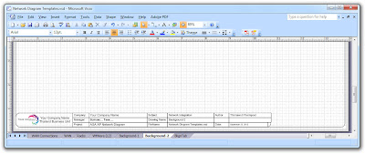
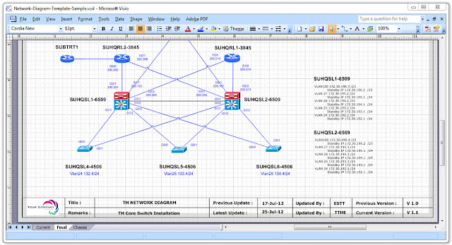
For example, if you want a background page that displays your company logo, or a title block that contains fields such as the creation date of a drawing, subject, Author, Drawing name, Filename, Manager, create these items and assign them to the foreground page. Let us see the example of what are on the visio after creating the Network Diagram Templates:
Network Diagram Templates Background 
Network Diagram Templates Background Network Diagram Templates BackgroundTemplates Background Insert Page
Diagram Templates Background

Wednesday, December 7, 2011

Network Security

       An enterprise network design must include security measures to mitigate network attacks. Fortunately, with the modularity of the Cisco Enterprise Architecture, you can address security concerns on a module-by-module basis. This section introduces the concept of a security policy, reviews various types of network attacks, discusses the elements of the Cisco Self-Defending Network, and helps you select appropriate security design components for the various locations in an enterprise network.

Network Security Concepts
       Organizational requirements and potential threats drive the scope of a security design. At its essence, network security measures should not only defend against attacks and guard against unauthorized access, these measures should also prevent data theft and comply with security legislation, industry standards, and company policy.

       Consider the following threats and risks facing today’s enterprise networks:

Threats:
  • Reconnaissance—A reconnaissance attack gathers information about the target of an attack (for example, the customer’s network). For example, a reconnaissance attack might use a port-scanning utility to determine what ports (for example, Telnet or FTP ports) are open on various network hosts.
  • Gaining system access—After attackers gather information about their target, they often attempt to gain access to the system. One approach is to use social egnineering, where they convince a legitimate user of the system to provide their login credentials. Other approaches for gaining access include exploiting known system vulnerabilities or physically accessing the system.
  • Denial of service (DoS)—A DoS attack can flood a system with traffic, thereby consuming the system’s processor and bandwidth. Even though the attacker does not gain system access with a DoS attack, the system becomes unusable for legitimate users.

Wednesday, November 30, 2011

Advanced SSH settings Cisco IOS

I mentioned about basic SSH setting in SSH@Cisco article. But I saw that there are other questions about SSH settings, so, I decided to dive a bit deeper. The settings mentioned below are tested with IOS 12.4, but I am not sure about exact version that supports below features.

Q1. What happens if I changed hostname or ip domain name after SSH settings has been done?
A1. Nothing. You need them to create rsa keys but, but afterwards, if you change them, only the key name changes and key data remain same.

ciscolab#sh crypto key mypubkey rsa

SSH @ Cisco

       Recently, I had to swap the Internet router of my company. BGP and cef ate up the whole memory and it was not possible to upgrade the memory of Cisco 3725 router beyond 256MB. It was time to change it.

       I had a chance to install a new Cisco 3845 with 1GB memory. Everything was fine except SSH access that I needed because of security policy. I searched the web and found “Configuring Secure Shell on Routers and Switches Running Cisco IOS” document on Cisco web site. It was a little bit different than current one. I made a configuration as explained, but it was not good enough and access to the router via SSH was not possible.

About one week later, I realized that
  • SSH only supports authentication with username/password, but it does not support just access password like telnet
  • So, I had to create a user and set a password with username command
  • I had to enable aaa new-model OR issue login local command under line vty for username/password authentication.
  • Also a hostname and a domain name were required to generate the keys, since router uses its FQDN as the label of the key pair.
  • SSH is enabled by default and I do not need to enable it myself.